Sunday, August 26, 2012

Building an end to end wireless sensor network

Building Wireless Sensing Networks - using Open Hardware.

Over the last couple of days, I have been busy setting up a wireless sensor network as part of the preparations in readiness for a web controlled central heating and energy monitor system.

The various hardware modules are all open source designs - and I chose to use a mix and match approach to the system which was put together using hardware from a variety of vendors.  Compatible devices were used from JeeLabs, Openenergymonitor and Nanode Ltd.

If you haven't looked recently, there are now new offerings of ethernet gateways, wireless sensor nodes and open data services from a number of providers - the smart wireless sensor arena is starting to get interesting.

Here's a brief description of what is needed. A fuller report will appear in a later post.

There are four main parts to the system:

1.   The Wireless Node or WiNode. Supplied by Nanode Ltd.


This is the system's analogue sensor, with 4 channels of 10 bit ADC.  WiNode can interface to a range of analogue inputs, such as thermistors for temperature sensing, current sensors or optoreflective sensors for detecting motion or occupancy  or even reading the dial on the gas meter. Additionally there are 4 channels of high current pwm driver which can be used to control relays, solenoids, dc motors etc. WiNode can be powered from a 5V USB type supply, or from a 9V-12V unregulated dc supply. Typically WiNode reads its analogue inputs every 5 to 10 seconds and sends that data wirelessly to the display and the ethernet gateway.

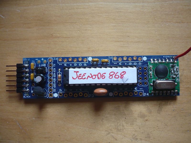
Whilst WiNodes can be bought from Nanode Ltd - for around £30, there are other compatible sensors such as the JeeNode available from JeeLabs and emonTX - an electricity monitor available from Openenergymonitor.  The JeeNode was the first device to combine the ATmega328 and the RFM12B - and  through Jean-Claude Wippler's RFM12 code library, wireless communication between devices has been made very simple to implement.  The JeeNode is the "barebones" wireless node - and this is reflected in the price - just 18.50 Euros - from the Jeelabs Shop.


Alternativley, if you are feeling keen, the basic microcontroller and RF module used on WiNode can be hand assembled on stripboard for about £10.  Here Nathan Chantrell shows  temperature sensors based on both the ATmega328 and a temperature sensing node based on the ATtiny. 

2. The second part of the system is the Ethernet Gateway. This is supplied by Nanode Ltd - and is known as the Nanode RF.


The gateway combines the microcontroller and wireless transceiver with an ethernet controller - in this case the ENC28J60.  The on board micro runs a simple client, which receives the data packets from the sensor nodes, and pushes them up to the web based server.

As well as pushing data up to the server, the Nanode RF makes the occasional request for server time. Once it receives the packet containing server time - it makes it available to the emonGLCD so that real time can be displayed. The time packet could be sent to all nodes in the system to synchronise their time - as WiNode has an on-board real time clock, which could be occasionally be reset to server time.

The basestation is supplied by openenergymonitor as emonBase, or you can buy it directly from Nanode Ltd as the Nanode RF for about £30.

3. The third part of the system is a local graphic LCD display from openenergymonitor.org.


This display allows you to monitor the wireless data from the sensors, and also can be used as a user interface. It has it's own temperature and light sensors, and two Red/Green LEDS which can be used to indicate physical conditions - such as too hot, too cold - or for energy monitoring applications high load and low load. In addition, the display has 3 user configurable push buttons - which can be used for screen and menu item selection.

Whilst primarily a display module, the emonGLCD also sends regular temperature readings up to the server, and also has it's on screen clock regularly updated by time requests to the server.

This display is obtainable from openenergymonitor.org as a DIY kit, emonGLCD for approximately £50.

4. The final piece of the "end to end" system is the cloud based application software running on a web server.  This program receives the raw data from the Ethernet Gateway, and allows it to be processed and visualised by the remote server. The very nice chaps at Openenergymonitor have written a very comprehensive server, data logger, visualiser, and analysis package called emonCMS.

Here is a screenshot from Nathan Chantrell - who has been using emonCMS for energy and temperature monitoring.

It just takes a few minutes to log in to emonCMS, obtain an api key and start to record and graph data from the sensor network. emonCMS was originally intended for energy monitoring, but it is versatile enough to manage a range of different data feed types and has a wide variety of data manipulation, graphing, visualisation and dashboard controls.


Saturday, August 25, 2012

Building Blocks for Wireless Sensor Networks


"Smart wireless sensor networks will bring about improvements to the quality of life, allow greater interaction  with everyday systems and lead to energy savings and better efficiency". Well - that sounds like quite a tall order, but if you care to look back over the last five or six years, and have witnessed the rapid growth in this area of technology, you will surely agree that wireless technology is now thoroughly embedded in many aspects of our daily lives.

What has brought about this quiet revolution has been the availability of low cost wireless hardware and innovative design. Wireless technology has very much become an area of innovation within the open source community, and the availability of low cost open hardware for experimentation has greatly assisted in putting smart sensors into the hands of the amateur enthusiast, hacker or maker.

One of the most innovative proponents of low cost wireless hardware undoubtedly is Jean Claude Wippler of JeeLabs. Over the last 4 years, jcw has blogged tirelessly about wireless networks, physical computing and ultra low power sensor networks. Not only has jcw had new and fresh material almost o a daily basis, but this material has been a living lab-book of all his experimentation and product development. jcw returns to his blog at the start of September after his summer break - and if you haven't got him on your list of "must read" now would be a good time to start.

jcw's main innovation was to come up with the combination of a low cost microcontroller grafter to an equally low cost wireless transceiver module.  By making the microcontroller the same as the one used by the Arduino community and writing a code library to support the wireless operation , this ensured a rapid and large uptake by the DIY market.   However, through the JeeLabs shop, this hardware was made available at less than 20 Euros, putting it well within the budget of the hacker and maker community.

Not only has jcw produced a fine platform on which to base wireless sensor designs, but he also single handedly has developed almost every possible add-on widget to enhance the basic sensor.  The JeeLabs shop is an Aladin's cave of low cost pcbs and kits - both in conventional through hole construction and in size reduced SMT format.

JeeLabs has inspired others to contribute to the community, and there are a number of open hardware designs based around the JeeNode core.  Energy monitors, internet gateways, sensor/actuators, tiny format sensors, graphic displays have all arisen from the original work by jcw.

For all the reasons above, I would like to show my respect and appreciation for all the work done by jcw in furthering the open hardware community.


A Small Success 

For anyone working with open hardware, there is always that great feeling when stuff comes together - and just works.

The latest example, is my recently acquired emonGLCD from openenergymonitor - as it's name suggests, a graphical LCD.  This display however has at it's heart an ATmega328 microcontroller connected to the ubiquitous RFM12B wireless transceiver - so it's an Arduino compatible wireless graphical display. How cool is that?

Well, actually, it's very cool, because the GLCD can provide a big, bold display of wireless sensor data, and it can also communicate with a web connected basestation and display text, data, messages -  even graphs from the internet.

So this evening's task was to build up the GLCD kit and get it to display data from my WiNode wireless sensor.

The build to just under an hour, and about another half hour to gather together all the various code libraries scattered around the web to breathe life into it and get a working display.  Assembly was very easy - assisted with the excellent pictorial and video build guide.

A few modifications to the emonTx (energy monitor) code - so that it worked correctly on the WiNode hardware, was all that it took to get the system up and running.

Tomorrow I will endeavour to get the emonBase  (aka Nanode RF)  to communicate with the system  and get some of the sensor data up to a remote server.

Central Heating  - Revisited

One of the areas in which wireless sensor networks have already made a visible impact, is that of energy monitoring, and there are numerous commercial products available for electricity monitoring, as well as some from the open hardware community.

However, whilst an electricity monitor may help you to shave your electricity bill by a few pounds a year - the area in which smart sensors could really make a difference is in the control of the domestic central heating system.

Here in the UK, where natural gas prices are always on the rise, and we are more reliant on overseas gas, almost every UK gas heated property is using a heating control system that fundamentally has not changed in effectiveness since the 1960s.  Most homes are still reliant on a time clock, a poorly located bi-metal thermostat and a couple of motorised valves - at the helm of controlling their greatest energy consuming appliance - the gas central heating boiler.

There are several key places where wireless sensors - and actuators could make an impact on the average domestic heating system.

Firstly - a better thermostat - one that is actually located in the room you wish to control the temperature of! So many houses had their thermostats located in the hallway - that draughty wasted space between the front door and the stairs. With a wireless thermostat, you have one which can be located in the room you are sitting in, and if the thermostat is a display unit like GLCD - then you can have instant feedback on the room temperature.

Radiators located in unoccupied rooms should be shut off, or at least to a minimum, when the room is not occupied. Clearly we don't want the risk of the room being freezing, but if the radiator is fitted with a thermostatic valve, we have the means of individually controlling when that radiator comes on, and to what temperature it heats the room.

By monitoring one a room by room basis, how the house responds to changes in external temperature it should be possible to construct a model of how much heat is needed to keep the various living areas comfortable.

Now that we are approaching the end of August, and with the "heating season" only about a month away, the aim is to put in place and prove, the main elements of an end to end web based smart heating control system.  By better informing the occupants, and finer control of the boiler and radiators, a saving of energy should be possible.

The WiNodes will be used for room temperature and water temperature sensing - and the high current pwm outputs can be used to drive power resistors - used to close down thermostatic radiator valves when not needed. The GLCD will be the user interface - located in the living room, - easy to get at, simple, intuitive and not buried at the back of some airing cupboard.

Gas Meter Monitoring

If you can measure it - you can control it

Most of us haven't got a clue of how much gas we use in a typical day - and how this can vary wildly with outside temperature.

With simple monitoring it is possible to obtain fine grained reading of the gas meter consumption.  I am fortunate that my meter has a reflective patch in the centre of the end zero digit - so I can use an opto reflective sensor to monitor when a unit of 10 litres of gas has been consumed.

With a better knowledge of when gas is being consumed, and how this relates to central heating, water heating and cooking activities will allow these activities to be better co-ordinated with lifestyles. For example if hot water is needed for a morning shower, then this tank heat up period should be incorporated into the morning heating period - when the boiler is already up to temperature and can take the extra load of the hot water coil, without loss of efficiency.

If a bath is required in the evening - then the heating controller should have a bath button - which heats the tank sufficiently for the bath or baths to be taken - and informs the user of when the bath will be ready.


Friday, August 24, 2012

WiNode - a technical summary


WiNode is the first standalone wireless sensor device from Nanode Ltd.  It is aimed at wireless sensing and control applications, and has a number of features not found on other devices. WiNode can form part of smart wireless sensor networks and be used in conjunction with a Wireless - Ethernet gateway such as Nanode RF.

Main Features

ATmega328 with RFM12B wireless transceiver operating at 433MHz or 868MHz

Motor driver IC for driving 2 dc motors, 4 relays or even a loudspeaker. Accessible via screw terminals.

4 general purpose analogue inputs with voltage scaling networks. Accessible via screw terminals.
Could be used for current transformers or opto-reflective pulse counters (gas meter).

microSD card – for datalogging or file storage. Can be used to store audio files for playback via loudspeaker.

32K battery backed SRAM – retains data during a power outage

Real Time Clock and Calendar with alarm wake-up function

At the core of Winode is the combination of the Atmel ATmega328 microcontroller and the Hope RF RFM12B wireless module. This is a tried and tested pair, used in designs by JeeLabs and Open Energy Monitor.  The code library to support the RFM12 is that written for the Jeenode – so ensuring 100% compatibility.

The new WiNode 4.0 design corrects a number of shortfalls in the earlier version and offers a compact yet versatile platform for wireless sensor application development.

WiNode is built on a compact 58mm x 66mm (2.3” x 2.6”) pcb, and retains the Arduino style shield connectors, allowing expansion by means of Arduino shields. However 100% compatibility cannot be guaranteed as WiNode uses several of the digital I/O pins for its own purposes. However for those wishing to add circuitry to WiNode, a prototyping shield on extended pin headers works well.

WiNode offers several additional hardware functions, not generally found on other Arduino-like platforms. These offer a range of functions considered to be useful to typical wireless sensor, actuator and control applications.

External Connections

Along the right hand edge of the pcb is a strip of 10 screw terminals.  This is where most of the interfacing to sensors and actuators would be made using simple wired connections.  These screw terminals offer four analogue inputs and four high current (2A max) motor or relay drivers.

Motor Drives

The WiNode has an on-board dual H-bridge motor driver – which can be driven with PWM for driving inductive loads such as motors relays, solenoids and even loudspeakers for audio applications.  Up to four relays, two reversing small dc motors or one stepper motor can be connected to these outputs.  The motor drive outputs are marked M1 – M4 on the underside of the pcb.  The motor drive channels are Digital 5, Digital 6, Digital 10 and Digital 11 – however restrictions apply on D 10 and D11 when accessing devices on the SPI bus.

Relays and solenoids can be driven, allowing the possibility of using WiNode for applications such as a wireless central heating controller, garden irrigation system, or solar PV monitoring system.  The dc motor outputs, used in conjunction with analogue inputs would allow WiNode to form the basis of a two-axis PV tracking controller – using dc motors for drive and potentiometers to read off the position.

Analogue Inputs

The analogue inputs are fitted with 10K input resistors, and a choice of potential divider resistor array.  Using the 4K7 array provided allows voltages up to 10.32V to be measured – or almost exactly 10mV per ADC count.  Fitting a 3.3K resistor array allows up to 13.3V to be read – making WiNode compatible with 12V battery systems.  The choice of this resistor array is left to the individual user, if the array is omitted, the analogue inputs will have a full scale of 3.3V – as WiNode operates at 3V3. The analogue input terminals are marked AI0 – AI3 on the underside of the pcb.  Analogue inputs AI0 and  AI1 have 160Hz low pass filters fitted (10K and 100nF) to reduce noise and transients. These may be omitted if not needed or if fast ADC sampling is required.
Power Supply

The screw terminals also provide connection to the power supply. This allows a dc supply of up to 12V to be connected.  If operating at 12V, the 7805 voltage regulator should be fitted with a heatsink – as should the 754410 motor driver IC. The external voltage input is marked Vin and 0V on the underside of the pcb.

If an unregulated external dc power supply is not desired, WiNode may be powered from a nominal 5V supply (eg USB) via pins 1 (0V) and 3 (+5V) of the 6 pin FTDI header. This supply is further regulated down to 3V3 to power the whole pcb – so WiNode could be powered from a small solar panel with a nominal 5V  250mA output.

Real Time Clock

WiNode is fitted with a Microchip MCP79411 real time clock/calendar.  This is a small 8 pin surface mount package soldered to the underside of the pcb.   The MCP79411 also contains an EEprom area where non volatile data such as Node ID, MAC address etc could be stored.  The MCP79411 also has an “alarm” output which can be used to generate a wake up interrupt or regular square wave output – interrupting the microcontroller on Digital input 3.  The WiNode pcb also allows a DIP version of the Dallas/Maxim DS1307 RTC to be fitted as an alternative to the MCP79411.  The RTC is battery backed by a 0.22F supercapacitor.

32K External SRAM

This is a static RAM connected to the microcontroller via the SPI bus.  It can be chip selected using Digital output 8.  The supercapacitor provides battery backup for this device.  The SRAM can be used for applications requiring temporary storage of moderate amounts of data, such as an audio sampling buffer (4 seconds of audio at 8kHz sampling frequency), or for short term datalogging.  The SRAM can also be used for program storage if the WiNode is programmed using Arduino TinyBASIC. Library routines to make the most of this external SRAM are currently under development.

Micro SD card

For applications requiring datalogging, or accessing files, a microSD socket has been included on the underside of the pcb.  One recent application of WiNode was as a programmable sound generator, where audio files were stored in the SD card, and played back through a loudspeaker, driven by one half of the motor driver H-bridge IC. If this option is desired, then additional 10uF electrolytic capacitors and 1 ohm resistors should be fitted to provide low pass filtering of the audio output.
Unfortunately, due to hardware restrictions, motor output 3 is not available when writing data to the SD card.

Summary of I/O Usage on WiNode 4

Dig 0  Serial Rx  to FTDI header
Dig 1  Serial Tx  to FTDI header
Dig 2  Interrupt from RFM12 wireless transceiver
Dig 3  Interrupt from RTC square wave or alarm wakeup
Dig 4  microSD chip select
Dig 5  PWM_2 output (M2) from motor drive IC
Dig 6  PWM_1 output (M1) from motor drive IC  - Green LED
Dig 7  Enable line for motor drive IC – held normally low to inhibit drive.
Dig 8  Chip select line for 32K SRAM
Dig 9  Unused
Dig 10  Chip select line for RFM12B wireless transceiver – also motor PWM_4 (M4)
Dig 11  MOSI signal for SPI bus  – also motor PWM_3  (M3)
Dig 12  MISO signal for SPI bus
Dig 13  SCLK signal for SPI bus
AN0   Analogue input 0 (filtered)
AN1   Analogue input 1 (filtered)
AN2   Analogue input 2
AN3   Analogue input 3
AN4   I2C data (SDA) for Real Time Clock
AN5   I2C clock (SCL) for Real Time Clock

Thursday, August 23, 2012

Wireless Sensor Networks - a review of devices


Photo:  the emonGLCD by openenergymonitor.org

The second part of a post reviewing what is available to the hobbyist in terms of open source hardware for wireless sensing networks.  This time I look at a series of kits that are compatible with the JeeNode from JeeLabs.

One of the key design challenges with any modern electronic device is the age-old problem of how do you get the power in and the data out?  A bi-directional low power wireless link solves the second of these problems, and innovative use of low power electronics, rechargeable batteries and possibly a tiny solar PV panel solves the first.

So with a low power microcontroller and a short range wireless transceiver you have the basis of a smart wireless node – which can be used for a variety of sensing on control applications.  The ability for it to communicate with web connected devices – via the wireless to Ethernet bridge opens up a vast number of possibilities for remote sensing and control. With the availability of open data services – such as Open Energy Monitor and Cosm, there is an easy route to get sensor data up to Cloud based servers from where it can be processed, graphed or mapped using appropriate data manipulation tools.

Having decided in principle upon a simple Ethernet to Wireless bridge, then comes the task of supporting a range of diverse wireless nodes. Range tests have shown that the RFM12 has a useful range of 100m in the household environment, opening up a whole host of possibilities for wireless energy monitoring, central heating control, solar pV monitoring or other wireless gadgets that just need to get a few bytes of data up to a central server.

Through suppliers such as JeeLabs, Open Energy Monitor, Wicked Device and Nanode Ltd there are starting to become available a wide range of compatible wireless devices aimed at low cost wireless sensing and control applications. These devices all use the RFM12 library code as developed by JeeLabs for the JeeNode, and generally devices from different vendors may be mixed and matched.
A short summary of some of the devices.

JeeNode


The original wireless node by Jean Claude Wippler of JeeLabs.  A simple combination of an ATmega328 microcontroller and RFM12B wireless transceiver on a small pcb.  JeeNode utilises the concept of 4 identical ports into which a wide variety of functional modules can be plugged to extend the basic system.  For full details see the comprehensive JeeLabs site.

emonTx

A development of the basic JeeNode, designed specifically for electricity monitoring applications.  It has 3 current transformer interfaces, and voltage, pulse and temperature inputs. emonTx forms the basis of the Open Energy Monitor – see OEM website for more information.  

emonGLCD

One  useful kit, is the emonGLCD wireless graphical display from Open Energy Monitor. This consists of a 128 x 64 pixel graphic LCD with an ATmega328 and the Hope RFM12 wireless transceiver. Whilst originally designed to display data from the energy monitor, the GLCD may be used to display any data – either that generated locally, or generated from a web based application.  The versatile GLCD has three user push buttons “Up”, “Down” and “Enter” allowing the user to select items or parameters from a menu an modify them, or select particular modes. My first intended application for the GLCD is as a user interface for a smart central heating controller.

In addition to the user push buttons, the GLCD has a LED backlight, a bicolour LED to show for example the status, and a LDR light sensor.  The LDR may be used to determine whether it is day or night, or whether the room lights are on – suggesting that the room is occupied.  To complete the usefulness of the device, an on board 18B20 temperature sensor allows the room temperature to be measured, allowing the GLCD to be used immediately for smart thermostat applications.  As with all the wireless devices offered by Open Energy Monitor, the GLCD is firmware compatible with JeeNodes, Nanode RF and WiNode.

WiNode

WiNode is the first standalone wireless sensor device from Nanode Ltd.  It is aimed at wireless sensing and control applications, and has a number of features not found on other devices.

1.  Motor driver IC for driving 2 motors, 4 relays or even a loudspeaker. Accessible via screw terminals.

2.  4 general purpose analogue inputs with voltage scaling networks. Accessible via screw terminals. Could be used for current transformers or opto-reflective pulse counters (gas meter)

3.  microSD card – for datalogging or file storage. Can be used to store audio files for playback via loudspeaker

4.  32K battery backed SRAM – retain data during a power outage

5.  Real Time Clock and Calendar with alarm wake-up function.

Air Quality Egg - by Wicked Device

This is a new development this year from our friends at Wicked Device and Sensemakers/Cosm.


Photo: Wicked Device.

On the right is the new Nanode RF SMT - by Wicked Device.  This is a much updated and improved version of the Nanode RF manufactured almost exclusively using SMT components.  The Nanode RF includes a 433MHz low power wireless transceiver and ENC28J60 ethernet controller.  Plug in headers allow Arduino type shields to be added to extend the system.

On the left is a stripped down Nanode RF - fitted with the Air Quality Egg sensor shield - a series of plug in gas sensors to allow measurements of typical air pollutants to me measured and sent up to a open data server - provide by Cosm.


Building Bridges


The advantage of having 2 weeks off to relax in a Somerset farm holiday cottage is that I now have time for blogging and new design work. The downside is that there is no internet at the cottage - so I am forced to come down to the village pub every lunchtime to deal with emails and online activities. The burden of this chore is lightened by the selection of good ales at the Horse and Jockey, Binegar, Somerset.

One of the key components in any smart sensor network is the bridge or gateway that allows the sensors to reliably exchange their data packets with the internet. The bridge needs to be robust and reliable in operation to make sure that packets are communicated efficiently with the remote server, and as such the bridge needs to run a tight service routine, and not get distracted by servicing local I/O.

Having made this realisation, it has become evident that a new Nanode device is required, one that acts solely as an Ethernet to RF bridge.  Nanode took the early decision to use the RFM12 wireless transceiver for all sensor communications – thus retaining firmware compatibility with Jeenodes, the Open Energy Monitor and the Air Quality Egg projects.

So following Oggcamp, and a discussion with Trystan of OEM, the idea of a dedicated Nanode RF Bridge was conceived, and this has now been added to the fold of Nanode designs. It is based on Nanode RF, but strips off all the unnecessary functionality, leaving just a bare bones Ethernet to RFM12 interface consisting of just 35 components.  The functionality can be reduced in general terms to the Magjack, the Ethernet controller, the microcontroller and the wireless module. Since there is no desire to interface with local I/O, there is no need to retain Arduino shield compatibility, and so the pcb can be shrunk down to just 42mm x 72 mm – giving a considerable reduction in PCB costs. A 26 pin (2 x 13 pin) connector at one end of the board allows I/O, serial port, ICSP to be accessed – but when used as a dedicated bridge, this is less likely to be used.

The ATmega328, as used in almost all Arduino compatible devices is restricted by just 2K of SRAM.  This limits the maximum number of wireless devices that the Bridge can effectively service.  If we allocate just 1K of RAM on the Bridge to service say 32 wireless devices, then each device has an entitlement of just 32 bytes for its “outbox”- the data packets being posted up to the server.

As well as node to Bridge communications, there will be applications that require node to node exchanges.  For example a node acting as a room thermostat may need to have its data acted upon by the heating control system, without going through the remote server.  Additionally, any wireless graphical display will want to monitor local nodes, and display data from them, as well as data that has been sent back from the server. Managing these local communications requires a fair degree of sophistication within the firmware.  

By removing the unnecessary hardware, the design is considerably simplified and cost reduced. In fact the Bridge has an intended selling price of just £20, which allows bundling with a WiNode and a programming cable for £50.

Tuesday, August 21, 2012

Oggcamp 12 - The open movement goes from strength to strength


Oggcamp12 is the fourth meetup of the Oggcamp unconference, this time held in Liverpool at the John Moore University School of Design.

Trystan Lea of Open Energy Monitor and I, travelled there together from Trystan’s house in rural Snowdonia, where I had overnighted after driving up from London.

Liverpool and the North West has a strong tech community, as anyone coming up from the South East will soon learn and appreciate. Trystan and I had previously attended the Liverpool BarCamp held last November at doesLiverpool, so it was good to meet up with old and new friends, from the Merseyside tech community.

As an event, Oggcamp12 was sold out, with 400 or so people packing the main auditorium for the opening talk.  Following on from the unconference format, there were two additional presentation rooms for parallel sessions, and new for this year, an open hardware jam gathering on the third floor.

Each year, Oggcamp attracts new followers and new presentations, and it was good to see the extent and mix of the talks being offered.  For anyone attending Oggcamp each year, it is a great opportunity to meet up with friends from previous gatherings, and catch up on what is happening generally in the open community. It’s not just Linux and open software, over the 4 years it has spread out to include open hardware, the Maker community, and a platform for presenting some of the wider thinkings of the open tech community.

There is so much going on at Oggcamp, so everbody comes away from Oggcamp with their own ideas and memories of what they saw and did.  I found it particularly difficult to choose between some of the excellent talks running in the parallel sessions, and so probably missed a lot of good material – including Stephen Fry’s video link-up presentation – doh! However, I did get to see most of Alan O’Donohoe’s (@teknoteacher) most inspirational talk on getting kids to code in schools, and a fascinating talk on the workings of the Enigma Machine.

The official hotel for Oggcamp was the Adelphi near Lime St. Station, but I missed out on the special deal and ended up in a satisfactory B&B in a very run-down neighbourhood to the north of the city centre.  A £5 cab ride to the city centre on the Saturday night, allowed us to pig-out on pizza before going on to the Adelphi for the evening of entertainment.  It was held in a large function room in the basement of the Adelphi, whilst at least 2 or 3 weddings were happening a floor above in the main hotel spaces.  You can tell a good scouse wedding – when at least 2 cop vans and an ambulance turn up at 11pm.  Musical entertainment was by @methoddan and his band, and this invoked some wonderful freestyle dancing, amongst the otherwise reticent geek community.  My only gripe about the evening was that the beer was either off, or crap (Tetley’s Extra) and the bar staff were a bit sullen. I stuck to bottled Bulmers cider all evening, apart from the point when I accidently ordered a Tetley’s, thinking “how bad can it be...?”

Sunday proceedings started around 11am, and having rather ignored the hardware workshop on the Saturday, I thought I’d better make the most of it on Sunday. Last year, the hardware consisted of just 3 offerings, myself with Nanode, some guys with a 3D printer and another lonely hardware guy.  This year about a dozen different organisations pitched up, and we had offerings including Textile repurposing and computer controlled embroidery,  doesLiverpool with Bubbilino, 3D printing, Raspberry Pi, Howduino with breadboard Arduinos and Fignition – a DIY Forth computer kit based on the ATmega328.

My contribution this year was a talk on the Saturday afternoon about the Nanode project plus some examples of projects where Nanode had been used in the last year – including the Malet St Gardens Sound Sculpture by Public Interventions, and the Air Quality Egg.

This was followed up on Sunday with a hardware workshop session where I built up one of the new WiNode kits, as used in the Malet St arts project, proved the wireless range from the 3rd floor workshop to the far corner of the JMU grounds (about 100m), and rigged up a Sharp motion and distance sensor so that those readings could be sent up to the Open Energy Monitor server.

OggCamp has become an annual phenomenon, and is growing from strength to strength. It offers an informal  forum for the open tech community, allowing community networking, presentations and entertainment all washed down with lots of beer and music.  Oggcamp doesn’t take itself too seriously, it’s just a bit of fun for those who don’t get out much.

Thanks to all the Oggcamp organising committee, and the Crew for all their hard work over the last 12 months, and this weekend, for putting on such an inspiring event. – see you all in 2013! 

Sunday, August 05, 2012

Distant Writing

A strange connection of internet links, which took me from steam engines to steampunk, delivered my attention on a couple of excellent histories of the electric telegraph.

The first is "The Victorian Internet" - a 1998 book by Tom Standage, describing the world's first online communication system.

The second is a most detailed account of the early commercialisation of the telegraph in London in the late 1840's "Distant Writing" by Steven Roberts.

Whilst some consider the telephone to be the most significant communications invention of the Victorian Era, it should be realised that the telegraph was already providing a service, a full 30 years before Alexander Graham Bell received his 1876 patent, and it was the telegraph network infrastructure that allowed Bell and several other notable contributors, to perfect the transmission of audio signals by wire.

It is technically ironic that analogue telephony arose from substantially a system of digital signalling, and how modern broadband, to carry our digital traffic has essentially been laid on top of the analogue voice network - at least for the last mile.

Standage's book describes how as far back as the 1890s - we had all the modern trappings wee associate with the internet,  from online shopping, social networking, romance, image transmission (facsimile) and hacking.

It is also noteworthy, that much of the punched tape apparatus developed for high speed telegraphy was adopted by the early computer pioneers for paper tape input and output into their machines - a trend that was to last right up until the mid-1980s, when magnetic disks became the preferred choice of portable data exchange. It was no surprise that the BASIC interpreter that Micro Soft  (note spelling)  delivered to Altair for their 8800 home computer system was supplied on a paper tape.

Curiosity

In a little over 12 hours time, the latest Mars Science Laboratory, and the Mars Rover Curiosity, will perform the most difficult and risky sequence of events of the mission to date - to effect a safe landing and deployment of the probe on the surface of Mars.

The 7 minute descent manoeuvre, and the 14 minute delay in communications between Mars and Earth - mean that it will be a very tense 14 minutes for all those following the mission - and the staff of the Jet Propulsion Labs in Pasadena, California.  This video 7 minutes of Terror, gives a good illustration of what the final descent and landing involves.

So far, of all the Mars surface probes launched, there has only been a 40% success rate of safely landing.  Lets hope that the $2.5 billion Curiosity bucks the trend, has a safe descent, and does not become the latest member of the exclusive Mars "Crash and Burn" club.

Space Exploration, or any kind of exploration, carries with it certain risk. The early Explorers of the New World, faced numerous perils, not to mention the arduous sea journey with the risk of shipwreck, disease, pirates or unfriendly natives.

I have recently finished reading an excellent history of San Francisco, which covers the 1830s to 1906, the Gold Rush and Boom Town years right up to the earthquake and its aftermath.  It is fascinating that in the 1840s, San Francisco was little more than a village of 500, and by 1852, as a result of the Gold Rush was almost 35,000.

Getting to California in the 1850s was a dangerous and long journey.  For the European, the journey could be over a year, by boat via the Isthmus of Panama, or the considerably longer journey around the Cape Horn.  For those that set out by wagon trail across the Mid-West, the perils of the Sierra mountains, often resulting in starvation and death by exhaustion - it was estimated that those who made it to 1850s San Francisco disease due to poor sanitation, overcrowding and violent crime 20% were dead within 6 months.

Compare this with modern long haul air travel, where we spend 12 hours in a 747, and the only discomforts we face are to moan about the food, the size of the seat and the disappointing choice of movies.

Having crossed the Atlantic four return times in the last 12 months, and peered out over the Sierras from 35,000 feet, it is hard to imagine what our forefathers endured, to fulfill their basic instinct of human curiosity.

California Dreaming...

                You certainly won't fail when you are the nearest restaurant to Pixar Inc.

It's been a while since my last post, and perhaps some readers might want to know what I've been doing for the last 7 months.

Last Autumn, I was invited to join a startup in Berkeley, California and be involved with biomass energy conversion  - notably wood gasification.

Shortly after Christmas, I left the UK to visit the organisation, and apart from a couple of brief returns to the UK, I have been out in California for most of the last 7 months.

My involvement with All Power Labs  goes back to February 2010 when I attended a wood gasification workshop, and got involved with a project to convert a Lister diesel engine to spark ignition such that it could be fuelled with woodgas.

In the last 2 years, APL has further developed their Power Pallet - a generator set that is fuelled from waste wood  - such as woodchips or nut shells etc, and are now manufacturing them at a rate of approximately 10 per month.  The Power Pallets are shipped all over the world, to provide personal and village scale biomass power production, and to communities that live off grid.


                                    Leaving the San Francisco Ferry Terminal

Gasification 101

Wood gasification is not a new technology, it's been known about since the early 1800s, and exploited in the early 20th century for providing motive power, by way of reciprocating gas engines, gasifying a range of carbon based fuels.  This reproduction of an early Paxman catalogue of 1913, shows the extent of the technology even 100 years ago. Below is a Paxman gas producer on the left, with the gas engine and scrubber. The engine is a type K - producing about 30hp.  The ladder on the left on the producer gives some idea of scale.


Gasification involves the thermal decomposition of biomass into a gaseous fuel, which consists of a mixture of the flammable gases hydrogen and carbon monoxide.  Air normally drawn in by the engine passes through the gasifier, where it gets converted to wood gas. This is then cleaned, cooled and mixed with further atmospheric air to form an explosive mixture which will run a spark ignition engine.

Converting wood to a gaseous mixture and running an IC engine in this way is far more efficient that running a steam engine directly on wood.  For a given amount of wood, you can generate approximately four times the electricity.  It also scales down to relatively small power outputs - and it is this small scale energy conversion that APL is currently involved with.

The "modern" gasifier was developed just around World War II, as a means of vehicle propulsion not reliant on petroleum fuel - and it is this modern, lightweight gasifier to which the APL design owes a lot of its heritage.

As a person with an interest in alternative energy and appropriate technology, the opportunity to work with one of the world's few gasifier companies, was one that I could not turn down - and so whatever else was going on in my life in the UK, had to be put on hold, as I pursued my Californian Dream.

In the next few posts, I'll try to give a perspective of life in today's California, and the ups and downs of  working with a startup 8500 miles from home.