Saturday, December 12, 2009

Wake Up Boo! -The 50uA Super Regenerative Transceiver


For the last few posts I've been looking at low cost wireless links and how you can hack them at home.

You might want to look at the previous posts, Take Control, Radio Days and Radio Gaga.

I first got started about 10 years ago working with 433MHz short range wireless devices for reading gas meters.
50uA operational current from a 1.5V Cell

Right now I'm designing a low cost transceiver which will allow any microcontroller to communicate with its neighbours but using a minimum of current from the battery - allowing smart sensors to last autonomously on small batteries for years, or to make use of solar cells or other energy harvesting techniques.

Here's my prototype low power transceiver built on a small breadboard. It's based around a Telecontrolli RT4 transmitter module on the left, a 74HCT14 CMOS Schmitt inverter in the centre and about 20 other components. The FTDI serial cable providing output to the laptop is on the top right.

The aim of this project is to develop a very low cost and low power wireless transceiver which can be used for short range smart wireless sensor networks. The cost of the transceiver could be as low as US$ 1.00 with volume production.

What's New

Following on from some of last week's ideas, I decided to make a couple of changes to the receiver. I've also managed to get the power consumption right down to just 50uA and the ability to run on a single alkaline cell. I've also had a few thoughts about using this design as a wake up receiver - hence the title of this post.

I've also got the circuit of this receiver captured in Eagle CAD and I am working on a board design - approximately 25mm square. If you want to share the circuit, please leave me a comment.

Changes From Previous Design

Previously I had been controlling the RF transistor in the super-regenerative stage by pulling down on it's emitter. This required an NPN transistor to turn the RF stage on and off.

It then occurred to me that rather than going in through the emitter, as per the Bolling and McEwan patents, the obvious way to control the RF transistor was via the base connection. This was even simpler - a direct connection to the data input pin on the Tx module, which connects through a resistor and capacitor filter stage and then onto the base of the transistor.

Thus I could eliminate the extra NPN switching transistor and simplify the circuit considerably. The advantage of this change, means that the receiver can now be made from an unmodified Telecontrolli RT4 module - further simplifying the amateur construction.

Even Lower Power Operation

I then decided to see if the receiver worked at lower battery voltages. Previously I had being using 3V, but I wanted to see how the receiver performed at 2V. After a bit of fiddling I can confirm that the receiver will still receive and decode 1200 baud data from a test transmitter located 10m (and 2 brick walls and a floor) away at 2V drawing just 98uA from the battery. I had achieved my first personal goal - the sub-100uA receiver, and one that would work in conjunction with a microcontroller running on 1.8V.

Not content with 100uA, I decided to find out what the lowest battery voltage was that would allow the super-regenerative process to occur- to determine just how low can you take the collector voltage on the Telecontrolli module before it just stops oscillating. With a fairly exhausted AA Duracell, I found that the lower operating voltage for the RF stage is just 1.2V. Any lower that this and the oscillator just won't start up.

A typical AA alkaline cell such as Duracell is 2700mAh capacity. With the receiver budget down at 100uA, this would mean about 3 years operating life on a single cell.

The bulk of the operating current is consumed by the RF oscillator. With a 100 ohm resistor in the supply rail to the Tx module I found that nearly 45uA was used by the RF front end, and only 5uA in the rest of the receiver circuitry. 45uA at 1.2V defines the lower operating point of the Colpitts oscillator, and this would be the fundamental limit to how low power this design could be made. Below 50uA, the receiver is getting to the point where it is no longer a useful receiver.

However, by lowering the baudrate of the signal, which means more energy per bit, it would mean that the receiver could be operated at a reduced voltage as a wake up receiver, waking the microcontroller, which then applies some more volts to the power rail, allowing it to become a fully functioning 1200 baud receiver.

A 300 baud signal would be suitable to detect in the wake up receiver. The filter capacitors needed for 1200 baud operation and 300 baud operation are likely to vary in value by a factor of 4. The correct capacitor needed for wake-up and normal operation could be selected using a pin on the microcontroller. I've now got the receiver running at 48uA and successfully receiving and decoding 300 baud packets.
Scope for Improvement

The scope trace shows the output from the second transistor running on a 1.3V cell at 300baud. You can clearly see the 1kHz nominal quench frequency superimposed on the 300 baud data. A better filter stage could be used to remove some of this making the signal easier to slice. With a bit of care and a suitable schmidt inverter it is possible to slice this data at the correct level and retrieve clean, square edged data. This raw signal is approximately 400mV peak to peak.

In each of these experiments I used my standard test transmitter which consists of another Telecontrolli RT4 transmitter module powered from a 4.5V battery and data pin driven by a PIC microcontroller. In order to make the tests representative of the real world, the test transmitter is located in the front room of the house and I work at the back - a signal path of 10m plus two brick walls.

Another thing I noticed whilst working at low supply voltages is that the relaxation oscillator slows down to about 1kHz, about 100uS on and 900uS off.

I tried sending a 1024Hz squarewave modulated RF signal from another test transmitter, and found that the output of the receiver was a squarewave signal equal to the beat frequency, between the relaxation oscillator and the 1024Hz test signal. This might prove a suitable means of causing a wake up. By choosing a wakeup signal that produces a strong beat frequency the resultant could be rectified, detected and used to wake up the micro.


Please leave a comment if you want to share any of this design or have any suggestions. I'd like to start a competition to see who can come up with the lowers power super-regenerative receiver. McEwan suggests that 1uA is possible - but I'm yet to be convinced.

Friday, December 04, 2009

Radio Gaga


For a few years I have been interested in short range wireless for smart sensor networks.

The two things that really interest me are firstly, a very low power receiver which could work on a few tens of microwatts of power - so would last significantly extend lifetime whilst running on a modest battery - e.g. 2 x AA Duracell.

Secondly a really cheap way of making a transceiver in such a way that transmit and receive functions share common parts thus leading to substantial savings in component cost and bill of materials.

Given these two goals, I set about my quest - a SAW Micropower Transceiver.

After some experimentation and breadboarding, I believe I have a simple design which could with some further development achieve these joint goals. The circuit is intended for smart sensor applications, which need to have a transmit capability, but their functionality could be greatly enhanced if they had a receive function too - especially if the incremental cost of providing the receiver is very low.

Working with such low power levels means that baud rates have to be low. The SAW resonator has a maximum switching frequency of about 4kHz so this limits the practical baud rate of these devices to say 2400baud - a standard baud rate that is easy to work and debug using a terminal programme. At 2400 baud, a typical 16 byte packet takes 66mS to transmit, which for domestic sensors for thermostats and appliance control is perfectly acceptable.

Working at even lower baudrates would allow even less power consumption in the receiver. The receiver could say fall back into a low power idle mode - where it can receive say a 300 baud wake up signal, which wakes the micro and reconfigures the receiver for 1200baud or 2400baud reception.

However, as is so often the case with electronics, it is a law of diminishing returns. You might have a great receiver that draws 350uA at 4V, but with 120uA at 2V it very much lacks in sensitivity - a lesson I learned by experience.

A US patent by Thomas McEwan was my first inspiration for a micropower super-regenerative receiver, but initial attempts to get this to work were something of a failure. However another trawl of patents turned up a few more interesting ideas. The result is a combination of techniques selected from the various patents.

A SAW Stabilised Transceiver

Dr. Eddie Insam describes in his Wireless World article how the super regenerative detector is very close in configuration to a Colpitts oscillator - which is used at the heart of most SAW stabilised transmitter circuits.

http://www.eix.co.uk/Articles/Radio/Welcome.htm

He suggests that you could start with a SAW based transmitter and convert it into a super- regenerative receiver. This is effectively what I have managed to achieve.

What sparked things off this week was a US patent for a SAW resonator stabilised super-regenerative receiver by Harold Bolling III, who worked for RF Monolithics - a US manufacturer of SAW devices

http://www.freepatentsonline.com/5751197.html

This uses a single port SAW resonator - just like the type used on most SAW based transmitter modules - such as the Telecontrolli ones I use.

I had previously failed to convert a SAW resonator based transmitter into a super-regenerative receiver - but this patent was the spark of information I needed. A simple modification to a standard transmitter module, and by driving it in and out of regeneration using an external PIC microcontroller, you get a passable super regenerative receiver.

Bolling's patent used a dual comparator and a quad op-amp in an elaborate timing and filter circuit for signal recovery - but as I could not get that part of the circuit to work properly, I ditched the ICs and decided to hack it with a couple of discrete transistors. This leads to a significant cost saving in components.

I have put this together on a breadboard, see top photo, and have a demonstrable receiver that initially used about 350uA at 3V controlled by a PIC. I have subsequently reduced this current to about 100uA.

When constructed from surface mount components, the whole design fits onto a board about 25mm square.

The range is pretty good for a super-regenerative receiver - at least 10m through two single brick walls - adequate enough for indoor devices such as room thermostats and remote switching of electrical appliances.

A simple I/O change from the PIC and the receiver reverts back to a standard 433MHz SAW stabilised transmitter.

The standard Telecontrolli Tx module uses 11 components, a typical super-regenerative Rx uses about 30. In my design, I take the standard Tx module, add a further 18 parts, which includes the PIC micro, a schottky detector diode and two NPN transistors and I get a complete 433MHz transceiver - costing under a pound to implement.

How it Works

At its simplest a super-regenerative receiver is an RF oscillator - usually based around a single RF transistor which is driven in and out of oscillation by an external quench signal which is normally between 10kHz and 200kHz. As the RF oscillator starts up, it exhibits considerable gain, and is very sensitive to any external RF which is coupled into the oscillator from an antenna circuit. If there is RF present, the oscillator will show a marked decrease in start-up time, or conversely it will use less supply current to reach a given level of oscillation - because some of the energy to achieve oscillation is supplied from the received RF signal.

In my implementation a PIC is used to generate an external quenching signal which is used to drive the Colpitts oscillator in and out of oscillation. This is a low duty cycle negative going pulsed waveform. In the first iteration this was a repetative rectangular waveform of approximately 10uS low and 90uS high. (This was subsequently improved to 16uS low and 354uS high - saving a lot of drive current). The quench frequency needs to be at least twice the baud rate of the serial data - as this is a sampled data system, both Messers Nyquist and Shannon need too be kept happy.

This pulse waveform is applied to the emitter of the RF transistor on the Tx module. The result is that the SAW stabilised Colpitts oscillator starts up and begins to increase its amplitude of oscillation exponentially. The output of the oscillator is capacitively coupled into the schottky detector diode, and it is given a light forward bias using a 10M ohm pull-up resistor. The schottky diode detects and rectifies the RF and this produces a series of negative going exponential pulses - of amplitude in sympathy to the detected RF. If there is a source of in-band RF energy, coupled via the antenna, into the Colpitts oscillator, then this RF will speed up the start up time of the oscillator, and the detector will reach full detection amplitude quicker but also be considerably slower to return to its quiescent state if RF is present.

This results in completely different pulse shapes emerging from the detector, depending on whether RF is present or not. From the change to the pulse shape, we get a change in the charge in the filter capacitor and from this we can amplify and recover the demodulated data. This detected pulse waveform is smoothed by a 2.2nF capacitor to reduce the level of the high frequency quench signal, the resultant being the demodulated AM data with an amplitude of between 10 and 50mV - see photos. This signal is then capacitively coupled into the base of the first external transistor via a 2.2uF electrolytic capacitor, where it is amplified to about. The NPN transistor is set up for a gain of about 25, with a 1M collector resistor and a 10M base biassing resistor to the collector. The output of this first transistor has data pulses about 500mV in amplitude and these are passed onto the second transistor to be squared up and brought up to logic level.

The lower scope trace shows the output from the detector when there is no RF present. The upper trace is the detector output when RF is present - a large change in pulse area. Timebase is 5uS and scope sensitivity is 50mV per division.

These traces are a little confusing because they are upside-down - an increase in detector output results in a lower level trace - i.e. things are inverted. By way of explanation - On the lower trace, when the pulse turns on the RF oscillator, the detector output rapidly falls, this is probably because the transmitter emits a pulse of broadband RF when it's first switched on. The oscillator then settles down to steady output shown by the exponential rise, which then levels out. However the oscillator is then turned off again by the rising pulse, shown by the short vertical section and overshoot at the end of the 12uS pulse. On the upper trace, the oscillator starts to stabilise, but is hit by a sudden input of external RF from the antenna circuit. This causes it to start to oscillate with greater amplitude than before, and this is characterised by the change in direction of the trace, becoming an exponential increase in detector output. Then the pulse turns the oscillator off, but the received RF still continues to produce detector output as the oscillator slowly ramps down to its quiescent state - which takes several tens of microseconds - upper trace. Thus the detector output has a much greater area corresponding to a significant change in voltage - this can easily be recovered with a simple RC filter circuit built into the first transistor stage.


Having an on board receiver will allow a smart sensor to receive configuration updates from the master hub, or receive and re-transmit message packets from other sensors. Additionally you could use a wireless bootloader and transmit firmware updates to the sensor via the wireless link.

Update 5/12/2009 - I later revisited the pulse generator timings, and settled on a low time of 16uS and a high time of 354uS, reducing the draw of the receiver circuit to just 170uA. It also allowed me to clock the PIC at just 500kHz - also reducing the power budget significantly. A means is needed to run the pulse generator autonomously of the PIC - such as a 74HC4017 decoded decade counter, clocked from the PIC's 32kHz watch crystal oscillator, or the internal PIC oscillator brought out to an I/O pin.

So, to sum up:

1. A super-regenerative (SR) receiver with an external quenching circuit, which turns on the RF oscillator for a short duty cycle of about 1:24 thus running on very low current. Less than 200uA for a 1200baud receiver running on a 3V supply.
2. A SR receiver that is made substantially from a SAW stabilised transmitter circuit, and at it's simplest, includes a 2 transistor signal recovery chain.
3. A SR receiver which uses a lightly forward biassed schottky barrier diode as a signal detector
4. A SR receiver which can be switched from receive mode to transmit mode by altering the logic levels on certain circuit nodes using the I/O pins of a microcontroller.
5. A SR receiver which can be implemented with sub-200uA current draw - opening up the possibilities of improved battery life.
6. A transceiver circuit which can be implemented in under 30 surface mount components on about 1" x 1" of pcb area
7. A transceiver that can be built in volume for under 1 US$
8. The SR functionality is almost "free" if a SAW transmitter is already used in the design.
9. A transceiver design that will form part of an open hardware smart sensor design.
10. A low data rate transceiver intended primarily for short range devices, smart sensor networks, control of domestic equipment and general use in the home.
11. A transceiver that can be modified to work in the various unlicensed bands, eg 315, 433, 868MHz.
12. A transceiver circuit which could be modified to incorporate a micro-power wake up circuit, using a voltage multiplier circuit formed from schottky diodes.
13. A transceiver that uses a voltage stabilised micropower relaxation oscillator to provide its pulse train.
14. A transceiver that uses micropower amplifiers made from CMOS inverters operating in their linear region as part of the signal recovery channel.

Power Management

In this version, the bulk of the 170uA is consumed by the Colpitts oscillator working on a 1:23 duty cycle. The PIC takes 550uA just driving the pulse stream - so a lower power method of producing the pulse stream is needed - possibly a 4017 decade counter running off the PICs 32kHz clock.

However, a better method is to use a single Picogate schmitt inverter, running as relaxation oscillator. With this oscillator taking just 20uA at 2.0V power supply - the prospect of a 100uA superregenerative receiver looks achievable. However - note that as the supply current is reduced, there will be a reduction in gain and sensitivity. It's all a case of tailoring the receiver performance to suit a given application.

The the two signal recovery transistors take just 20uA, but could be replaced with a single Picogate CMOS inverter, run in its linear region - see McEwan's patent. This provides high gain at very low power levels at only a small price premium over the two transistor solution.

McEwan's patent US 5630216 can be found here:

http://v3.espacenet.com/publicationDetails/biblio?DB=EPODOC&adjacent=true&locale=en_EP&FT=D&date=19970513&CC=US&NR=5630216A&KC=A

Whilst the PIC is in low power sleep mode, the receiver could be run as an even lower power wake-up receiver. The output amplifier/transistors could be used to amplify the output of the schottky RF diode voltage multiplier circuit. The wake up circuit would respond to a low datarate packet added to the beginning of the packet sequence, and this would interrupt the microcontroller out of sleep mode and enter the normal super-regenerative receive mode.

See Fig 3. here for details of 5 stage voltage multiplier circuit for receiver wake up design.

http://www.mobnets.rwth-aachen.de/fileadmin/templates/images/PublicationPdfs/2008/RTWAC-PIMRC-2008.pdf

Extensions to the Basic Design

The basic receiver has been built on a small prototyping breadboard using a Telecontrolli transmitter module as the starting point. This keeps all of the RF circuitry in one compact module with a good groundplane. The original design used just 15 components plus the PIC. Whilst the original used the PIC to generate the pulse train, this was to power hungry and so a low power alternative has been found. Some additional components have been added to make a more reliable design.

A 74HC14 Schmitt inverter has been arranged as a relaxation oscillator, to provide the train of pulses to energise the receiver. To get this inverter to run on minimal power a stabilised 1.2V power supply has been fashioned from three diodes in series fed from the battery rail with a 220K resistor in series and a suitable reservoir capacitor. The pulse output is fed into an NPN transistor and this pulls on the emitter of the RF transistor in the Tx module. This oscillator uses less that 8uA when running. The timing resistors have been chose to give an on time of about 20 to 30uS and an offtime of about 380uS. The total pulse train should not exceed 415uS - if you want to successfully demodulate 1200 baud. The relaxation oscillator is very voltage sensitive, so it is imperative that it is run from a diode stabilised supply - so that performance does not change radically with battery voltage.

Taking a hint from McEwan's micropower amplifier built from a 74HC04 inverter, I incorporate this as a pre-amplifier which follows the schottky RF detector diode. Whilst it is possible to provide sufficient gain after the diode detector from just two NPN transistor stages in series, as was achieved on the prototype, the preamp gives much better performance when working with weaker signals. As per McEwans patent notes this preamp runs on a stabilised 1.0V supply and draws literally a couple of microamps.

The signal recovery chain then consists of a series of three NPN transistor stages, the first to re-invert the output from the pre-amp, and the following two to provide filtering and data slicing so that the output of the receiver is compatible with 3V logic inputs on the microcontroller.

These additional features can be very economically implemented using Picogates - single CMOS gates in SOT23/5 surface mount packages.

Getting the receiver to work reliably on breadboard has been a little tricky - but as this was just to prove the concept, I can now move to a pcb design.

I have commenced a pcb layout of the transceiver using Eagle CAD, which appears to be a popular choice amongst the hobbyist community - thus making the design more readily available to those who wish to tinker. The complete transceiver fits into 25mm x25mm which makes for a very compact design if you include a surface mount PIC or AVR.

Further Ideas.

This prototype uses a pulse train to switch the emitter of the RF transistor thus driving the Colpitts oscillator into oscillation. It is probably equally viable to apply the pulse train to the base input of the RF transistor, which saves a little complexity and modification to the Tx module.

If you can accept a lower baudrate, the power consumption can be much reduced by reducing the frequency of the pulse train. This is done by increasing the off time. At 600 baud, we could afford to be on for 30uS and off for 800uS - initial experiments showed that you could get the RF front-end consumption down to50 to 60uA.

The signal recovery chain could be implemented in McEwan style, micropower amplifier stages using CMOS inverters. However you get just as many NPN transistors for the cost of a hex inverter IC.

McEwan's design used a pulse shaping network to drive the emitter of the RF transistor with a train of negative going exponential pulses. This had the advantage that it drove quite high currents into the emitter just enough to kick it into oscillation. He also claimed to be able to run the RF transistor with about 220K of resistance in the collector - forcing the RF oscillator also to work at very low current levels. I have not yet had any success with such a lightly biassed RF stage.

Sunday, November 29, 2009

Radio Days

Some Thoughts about Low Cost Wireless Networks

This is the first of a few posts looking at short range wireless devices. I've experimented with these for a few years and believe that there is a requirement for a really low cost transceiver which allows smart sensors to communicate with each other. In the first of these posts I will look at simple super-regenerative receivers which I have encountered already by pulling apart devices such as wireless doorbells. These can be quickly re-purposed by adding your own microcontroller, which is what I did with the Lidl remote control socket.

Compared to WiFi and other 2.4GHz systems the 433MHz link is cheap and tacky, but it serves its purpose adequately. It offers a very low cost means for devices to get small amounts of data across a wireless link. It is used often in wireless doorbells, remote control systems and burglar alarm systems.

The Lidl remote socket used an example of a super-regenerative receiver and my transmitter pcb uses a SAW stabilised single transistor amplitude modulated (On/Off keyed) transmitter from Telecontrolli. The link runs at a pedestrian 1200 baud - it's best to always pick a standard baudrate to make it easy to debug with hyperterminal. 1200 baud is perfectly adequate for sending a few relay commands and temperature readings around the house.

Super-regenerative receivers are designed to be very cheap - but they can lack in sensitivity. They use a technique discovered in the 1920s by Edwin Armstrong, when manufacturers wanted a cheap wireless that only used one valve. Here's some Wikipedia info for those interested in early super-regenerative sets

http://en.wikipedia.org/wiki/Regenerative_circuit

Today this has translated into one active RF transistor but the principle is the same. A super-regenerative receiver is small and cheap to make often using less than 30 components.

The transistor is configured to be a 433MHz RF oscillator and is biassed up so that it is just on the point of oscillation. It is swept through this oscillation point using a lower frequency of a few tens of kHz. Any incoming RF signal will add to the RF transistors desire to oscillate, and this appears as a change in collector current. An op amp or a chain of 3 cascaded transistors is usually used to detect this change in current, and turn it into a logic level pulse which follows the detected signal exactly. The result is a signal that you can feed into a micros input pin and begin to decode the serial bits.

The super-regenerative receiver has at its heart an RF oscillator. In the 1920s super regen receivers could re-radiate and produce a lot of interference picked up by neighbouring sets. This might be seen as a disadvantage - but its not a million miles from what you need to automatically transmit a packet of serial data. In fact some cheap super-regens emit so much RF carrier that they can cause other signals to be blocked. When not receiving, this RF oscillator could be re-purposed to be a low power transmitter. In theory you could have a whole 433MHz transceiver costing about $1 to implement. This would be a really scungy transciever with only about 10m of range - but if you are using it in a network with other sensors which can retransmit messages, then in theory you could bounce your packet across a series of nodes and thus get to the gateway as a series of short range hops.
Super-regen designs are compact. With only one or two active components and 25 or so passives, they can fit onto a board the size of a postage stamp. They can also work at very low power - just a few microamps. There's a great patent for a super-regen by Thomas E. McEwan for a receiver that works down to 1 volt supply and 1uA of current

http://www.freepatentsonline.com/5630216.html

This makes it ideal for battery powered sensors which have to work for years from a single cell - or power harvest, from mechanical vibrations for example.

I had a go at copying the McEwan design - it worked to a point and had a range of about 3m when using a standard doorbell push as the transmitter. I suspect that it was working more as a crystal set than a super-regen though.

There is an renaissance in Super-regen designs as they can be implemented in silicon within the actual chip. This makes them ideal for say 2.4GHz bands where the antennas a much smaller. Such devices could be used as RF transponders for RF ID devices. They could possibly even harvest their operating power from the RF energy they receive - stored in a super-capacitor.

Super regenerative receivers are used in wireless doorbells, thermometers, remote control toys and other short range wireless gadgets. The photos show a commercial Laipac super-regenerative module and two doorbells - one in discrete through-hole components and the other in surface mount. These discrete designs will work at currents down to about 300uA.
The Laipac design is documented on the web and uses 2 transistors and an LM358 op-amp comparator device. The older doorbell achieves the receiver in just 3 transistors, and the newer doorbell does it with four. All low cost super-regens generally use a fixed capacitor and slugcore-tuneable inductor to get close to the required frequency. The inductor is clearly visible as the red plastic component on the back of the Laipac design.

Super regenerative receivers are also very easy to hack - in fact I first hacked one from a wireless doorbell I bought in Wilkinsons for under a fiver. You just have to find the serial output data - which is easy if you have a scope, or at a pinch a logic probe. Just connect this to your micro and start coding.

There's a well informed article about super regenerative receivers by Dr. Eddy Insam - well worth a read if you want to pursue them further

http://www.eix.co.uk/Articles/Radio/Welcome.htm

Eddie Insam talks about combining a super regen detector with a SAW stabilised transmitter device to make a cheap transponder or transceiver, but gives no detail away. He also mentions hacking a SAW stabilised transmitter module to make it into the heart of a super-regenerative receiver - tricky, but do-able, he says - I wish he would share some of that detail.

Over the next couple of posts I will share some of my recent findings.
Saturday, November 28, 2009

Take Control

For some time I've wanted to tinker around with using the internet as a means of monitoring and control.

There's an appreciation that the growth in internet applications will likely be for internet connected devices - The Internet of Things, Web 2.0, or in sci-fi speak "The Rise of the Machines". Whilst not quite in Terminator league, I thought I'd get an internet dev board from Microchip and see what I could cook up.

The first step was to connect it up to a low power wireless transmitter, so that it could extend the scope of its control, beyond the confines of its own pcb.

I'm fascinated by minimalist solutions, and also hacking old gadgets to improve their performance or functionality. I like the idea of a network of very low cost wireless sensors scattered around the house, such as temperature sensors in every room linked to motorised radiator valves - all of which can be monitored and controlled remotely via the internet.

The key thing is that the sensors can talk to each other - regardless of the type of microcontroller make or model. So they need a standard serial communications protocol that they all can generate and decode. This protocol needs to have a low overhead to run on the smallest of micros with limited on chip resources and simple to hack and debug - more on this later.

I've coined the term "CheaperNet" to describe this network of low cost sensors, and so to get me started, I first needed a low cost candidate to be the first CheaperNet application.

There's a Homecamp Christmas party coming up soon, with talk of internet connected Chrismas lights - so I thought I'd hack together an internet controlled mains switch by way of a demo for a "show and tell" session to illustrate some of the virtues of CheaperNet.

This involves several stages of connectivity. Firstly using the PIC dev board which hosts a micro web server, using the free Microchip TCP/IP stack and the HTTP2 sever application that comes with it. This board acts as a kind of hub/gateway device onto the CheaperNet, and then radiating out from this hub is a a 433MHz wireless link to individual sensors. The first of these being the remote controlled mains socket. Plenty opportunities for a good hardware and firmware hack.

As stated, the PICDEM.Net dev board acts as a micro webserver. This is an almost "out of the box" solution requiring very little configuration to get you connected. The harder step would be to hack it to control a wireless link to a remote control socket which turns the electrical load on using a relay. Fortunately the PICDEM board has some LED outputs which can be turned on and off from the net, so if I could sense one of these I/O pins changing state and generate a wireless message to turn the remote relay on, it would be a simple enough hack.

The PICDEM board is a stupidly big board for what it does. All you really need is the £5 PIC in the middle and the ethernet connector. The little board below could also be dumped if you drive the 433MHz wireless transmitter straight off the I/O of the larger PIC.

The idea being that I can display my live electricity consumption in one browser window, and at the same time click on a button in another browser window that activates the Internet Socket turning something on - so that you can see almost immediately the effect on the live power trace.


A bit geekish perhaps - but worth a challenge. Good way to turn the Christmas lights on at the forthcoming Homecamp party.

The first thing to do was to salvage the old unreliable remote control socket that I purchased as a set of 4 from Lidls a few years ago.

These consist of a 433MHz super-regenerative receiver, a microcontroller and a mains relay all packaged in a plug in plastic case. Unfortunately, these suffer from any old 433MHz interference will cause them to turn on, or off, because of a very poor wireless protocol, which is readily confused by any other wireless devices nearby.

The solution was to implement a simple wireless protocol called SNAP at each end of the wireless link, and bodge a new microcontroller into the spare space in the plastic case. Probably the closest thing this cheapo Lidl switch has had to a brain transplant!

The existing Lidl microcontroller is dumped and replaced with one a little less stupid. The Lidl decoder was very prone to falsely switching when some other 433MHz transmissions - like the neighbours door bell started transmitting. I'm using a PIC16F88, solely because a have a few of them lying around the workroom and I have the beginnings of the SNAP wireless protocol already used on a past project


So after a few hours on Friday, I got the wireless protocol to work, and a few hours today got the unit together with new brain and a suitable wireless interface on my micro webserver dev board and voila I now have a desk lamp that can turned on and off from anywhere on the planet - or perhaps beyond.

This is a SnapRat board - just a PIC16F88 with a 433MHz wireless transmitter. I designed these a few years ago to make a solar powered wireless compost heap temperature monitor - definitely a world's first.

When you click on the 8th LED button on the web page, the micro on PICDEM board raises on of it's I/O pins (to light a real LED) I use the SnapRat board to monitor this and send a "relay-on" message to the receiver and PIC inside the remote socket. This turns the relay on - at a distance of about 20m indoors.

Some of the detail.

The PIC micro web server uses the Microchip TCP/IP stack. There are several dev boards which run this stack - such as those from Olimex or Celeritous.

I use a PIC16F88 to run the wireless protocol at both ends. The protocol is called SNAP (Scaleable Network Address Protocol) and details can be found on the High Tech Horizons site www.hth.com/snap/

I use a PIC implementation that is based on the published code by CASTRICINI & MARINANGELI - originally written for a PIC16F84. (See the HTH site). The whole protocol fits into about 850 words of ROM including the serial transmit and receive bit banging routines, error handling etc.

SNAP was designed to be a minimalist protocol to run on small micros. There are versions of it for BASIC Stamps and AVRs. Someone has bound to have hacked it onto an Arduino - if not - please would someone rise to this challenge.

If you want to see my firmware - leave me a comment.

Sunday, November 15, 2009

Using an Arduino to monitor gas consumption

Energy monitoring is something I have been involved in for ten years - both professionally and "socially".

First a Historical Note - this formed the basis of my "off the cuff" talk, "Gas c.1999" at Homecamp 09.

Back in 1998, whilst working for a telecommunications equipment company we needed to develop a low cost gas datalogger for automatic meter reading (AMR) applications. It needed to read gas meter pulse counts from a Schlumberger meter and transfer them via short range wireless and good old fashioned PSTN telephone modem to a remote PC based server.

The wireless transmitter had to have a battery life of 10 years, running from an AA sized lithium thionyl chloride cell, and the low data-rate modem had to be self powered from the telephone line. That, plus the need to store gas meter readings every 6 minutes for 16 months made it quite a design challenge. Oh - and it has to be intrinsically safe to use in the hazardous zone around gas meter installations.

A two part product that featured a short range radio, a telephone network connection and had to meet the requirements of Ex intrinsically safe equipment meant that dealing with the various approval bodies was a major part of this product and not the actual engineering itself.

Technically the project was a success. Fine resolution gas meter data automatically retrieved from a number of trial sites. But at £40 a unit, it wasn't the low cost the utilities wanted - when they were only paying £5 a year for their small contract army of meter readers. The project was shelved in late 1999 - conveniently on my workshop shelf.

So now we have "Gas c. 2009" - the subject of a possible future Homecamp off the cuff presentation.

In the intervening decade, things have changed somewhat. Low power radio gadgets are now commonplace, and low cost energy monitors have been available for a few years now. (Electrisave, Owl, Wattson, CurrentCost etc). PSTN modems are well and truly a thing of the past, as broadband has all but taken over as the means of getting data out from low cost sensors.

In addition to these technical changes, several cultural changes have occurred in the last decade. Thanks to the efforts of a group of pioneering computer scientists working for IBM, Hursley - it's now cool to monitor your home energy usage , and the Homecamp unconferences have shown that I'm not the only one with an interest in energy monitoring - (and I thought that I was the only geek in the village. Of course it is a global village now - with a lot more residents).

Counting pulses from a gas meter became a whole lot easier when some meter manufacturers started to provide an opto-reflective silvered zero on the least significant digit of the register. Prior to this, there was a little red rotary pointer which was almost impossible to detect reliably via optical means - unless you were lucky enough to have a Schlumberger meter which came already fitted with an RJ11 connector and a reed-switch providing a "volts free" pulse output.

Technically, Transco, the gas transport company own everything up to and including your meter. If you want to measure the pulse output, they would provide a "Chatterbox" - a Ex certified relay box, which echoed the pulsed on to your own equipment. It was powered by 4 alkaline D cells. Transco would charge you a fixed cost of about £500 to come and install this unit. This proved an obvious deterrent for all but the most determined energy monitoring enthusiasts. This issue needs to be addressed if we are to make much headway in monitoring gas consumption. Nobody wants to pay £500 for a clunky old relay box that cost £20 to make. What is needed is a low cost, Ex certified, universal pulsecounter, which anyone can fit and geta pulse count from. Wireless seems the obvious choice - an opto sensor that sticks to the front face of the register and a self contained 433MHz transmitter running of a lithium cell. Essentially fit and forget.

The turning point for me came in November 2004, when my gas utility replaced my old meter with an Actaris, "pulse ready" meter. This had the opto-reflective silvered zero, ready provisioned to accept a photo reflective sensor. Sometime in Winter 2004, I put one of these together on a small scrap of veroboard, and then wrote a pulse counter routine in PIC assembler. However, come the spring, and a new extension to the house, and the whole project was forgotten and the pulse sensor lost.

So a couple of weeks ago - I decided to make another. I still had some of the photo-reflective IR sensors left. This time the coding would be a whole lot easier. In the intervening 5 years, I had learnt just sufficient C code to be dangerous - prompted by the arrival of the ubiquitous Arduino. The timing was right an announcement of a forthcoming Homecamp in about a month, meant that I had to pull my finger out and get hacking.

Here's the photo-sensor on a small scrap of veroboard - pushed onto a couple of locating pegs conveniently provided by Actaris.

The 4 wires are 5V supply, LED supply, photo transistor output and ground. I use an additional NPN transistor to buffer the voltage output and give me a bit more gain and sensitivity. Connect this into an Arduino ADC input and start sensing digits.

So the first thing I did was write a simple ADC routine which prints the ADC value to the serial port once per second so that I could see what was coming out of the sensor. This I captured in hyperterminal (aargh) and plotted out in XL - shown below. From this I could see that there was a very characteristic voltage pulse produced when the zero went past the sensor - but additionally all of the other digits had their own signature too - so with a bit of coding I could sense to the nearest litre.

A few lines of Arduino code, I had the pulse counter running, outputting the pulse count every second along with an (approximate) H:M:S timestamp. Having let this run overnight and during the time that the boiler fires for the water heating and central heating I had 60,000 readings which could be chopped into manageable chunks and graphed in XL. However this is such a tedious way of processing data so I thought I'd try something a bit more sophisticated.

I'd had recently acquired a CurrentCost CC128, and subsequently had been using Dale Lane's CurrentCost GUI for capturing the output of the CC. Why not write a sketch for the Arduino that mimics the CC XML data format, and then squirt this into Dale's GUI? Excellent idea and about 30 minutes of hacking the XML as a serias of serial print statements (thanks to CurrentCost for making their XML output format freely available on the Web) I soon had the Arduino interloping as a gas monitoring CurrentCost.

Individually, Pulse counts can be unspeakably dull. It's only when you get two of them, which are different, and separated by a suitable time period, that they become remotely interesting. If you take a reading at the same time each day, for example, and subtract them, then you get your daily consumption. If you shorten the sampling period from 24 hours to 1 hour, you can get a much finer resolution of when your boiler fires and how much it uses. You then extend this a bit further and start taking readings every 6 minutes and the picture becomes a lot more interesting. With 6 minute resolution you can see when the gas is being used, and by logging room temperature and external temperatures on other channels, you can start to see how quickly your house warms up, for a given outside temperature as a function of the gas you burn. Every house will have it's own thermal lag characteristic and once you optimise for this you will start to use it to your advantage and make reductions to your gas consumption - well that's the plan.

Real time boiler logging is a useful tool for diagnosing the defects of an existing system. In 2005 I made the poor choice of buying a 24kW condensing boiler. Had I bought a 12kW, it would have been more than adequate for my property and spend less time idling and modulating down to a lower power output. As with over powerful, fuel guzzling V8 cars - big is not always best.

Here's the first plot I got from Dale Lane's GUI showing the boiler modulating down as the return water temperature starts to heat up. The horizontal scale is 20 minutes and the vertical scale is from 8kW to 20kW.

Each pulse on my meter is the passing of 10 litres of gas. Gas is about 39MJ/m3 so by dividing 390,000 by the time between consecutive pulses, you get the instantaneous boiler power in kilowatts. Flat out, it takes about 16 seconds between pulses for my boiler - so I can deduce that it's consuming gas at about 24.4kW

Possible extensions: I have a couple of 10K pipe clip thermistors I got from Rapid Electronics. I'll use some of the spare Arduino ADC inputs to measure these and the internal and external temperatures.

I use a 433MHz Drayton Digistat to control the boiler. Having already cracked the "boiler on " and "boiler off" wireless packets using a PIC, I can get the Arduino to control the boiler.

Write a 3 term PID controller to control the boiler temperature - one that avoids massive overshoot, and consequent waste of gas.

I'm also currently hacking a "cheapernet gateway". This is an attempt at a very low cost ethernet gateway not dissimilar to an Arduino ethernet shield which will allow low cost wireless sensors to connect to the net and provide the means for realtime, live energy monitoring. Real time means once per second data (OPS) with a 2 second delay caused by the interweb thingy.

Friday, October 09, 2009


It's a while since I last updated this blog, but I have been working towards a more sustainable household.

This month I completed the installation of a wood fired stove with back boiler - returning a solid fuel heatsource to a previously abandonned fireplace.

The stove provides heat for the living-room - the most often occupied room, and heat from the boiler is conveyed upstairs to warm the bedrooms and the hot water tank.

The stoves burns about 1kg of well seasoned wood per hour, so a good armful of logs will keep it going all evening. We have been fortunate enough to obtain several tonnes of firewood from a fallen oak tree which should keep us going for a while.

The woodstove and boiler is a self contained system and needs no electricity to operate, unlike the gas boiler which needs power for it's control board, ignition, fan and circulation pump.

Once lit, it gets the room comfortable within about 20 minutes, and needs no more than adding a couple of logs per hour to mantain it.

It's just another element in my design for household sustainability. The cost of gas can go through the roof, and the electricty can go off but we will still be cosy in winter. The installation was designed to allow the stove to contribute to the existing central heating system, yet operate independently if necessary.

The cost of the complete system, including a stainless steel liner for the chimney, plumbing, plus a new stone hearth and brick fire surround was about £1600.

Sunday, September 23, 2007

Renewable Enegy Workshop Comes On Line

This year I have been building a new workshop that will give me much needed space to work on my various projects but also acts as home for my renewable energy developments.

It replaces the old engine shed that I used for a couple of years, and it puts all my technical equipment under one roof - with the solar water heating panels on top.

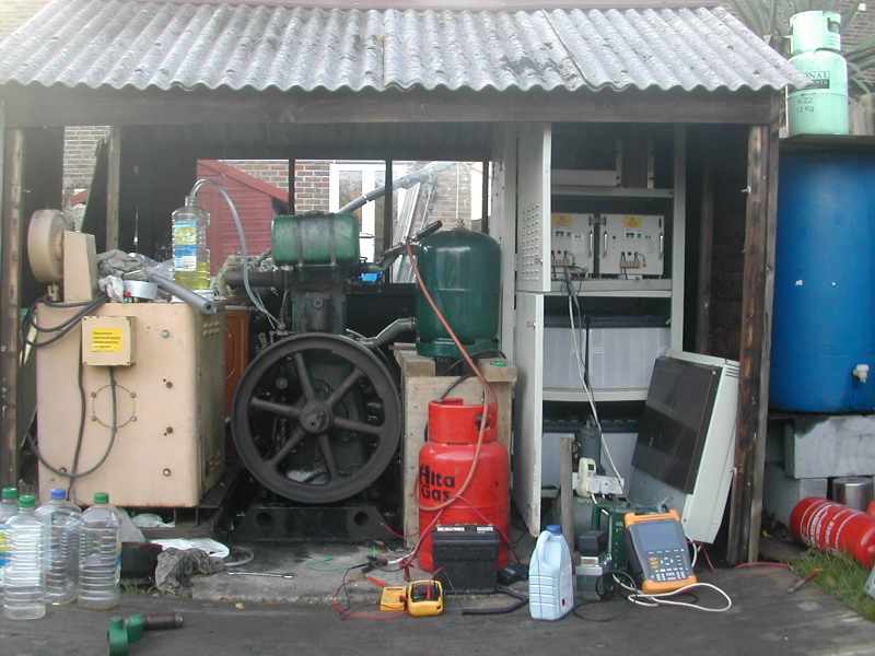
On Friday, with the Lister generator in place and plumbed up with cooling, batteries and inverter, all was ready to start up the generator on vegetable oil and make real heat and power for using in the house.

The generator was started around 1pm and run for about 3.5 hours. During that time it heated a full tank of hot water, ran a 1700W electric storage heater to warm my office throughout Friday afternoon and evening, and powered the two PCs and other equipment in the office. During this time it used about 4 litres of waste vegetable oil.

The office has been running all weekend from the battery powered inverter and already it has started to show a 25% reduction in the amount of electricity that I use from the grid daily.

As my experience and confidence grows, I will run the engine for longer periods and use it to power more of the household appliances, in particular the dishwasher and the washing machine which are otherwise quite heavy power users.

The next step is to complete the changes to the pipework which will allow the heat from the engine to contribute directly to my central heating system, which will make more efficient use of the waste heat generated by the engine and also start to reduce the amount of gas I use for home heating.

Learning to Fly - but I ain't got wings


One of the things I wanted to do before my 40th birthday, was to have an introductory flying lesson in a light aircraft.

Well I missed my mark by a couple of years, but on Wednesday 10th September I realised my ambition and took a half hour trial flight in a Cessna 152.

Fortunately we have an aerodrome in Redhill about 2 miles from home, and Harvard Aviation runs a flying school from out of an old WW2 mess-hut.

They have a fleet of four or five Cessna 152 single engined, two seaters that they use for most of their flight training.

These planes were built about 25 years ago, and inside have the feeling of an old British sports car, noisy, flimsy and very cramped, sitting with shoulders touching in the narrow cockpit.

After a brief introduction to the controls, and a few pre-flight checks, we set off across the grass towards the airstrip. After getting clearance from the tower, we trundled across to the end of the strip and took off to the west. After performing a 180 degree turn over Redhill and gaining 1500 ft, the pilot handed me the controls and had me keep it straight and level for the next ten minutes or so.

This was my first time ever in a light aircraft, and I found the controls so light and responsive, that it took all my concentration to remain focussed on the distant level horizon and correct the minor movements of the aircraft.

Our flight took us to the east following the Redhill to Dover railway line, although I had no time for sight-seeing. As we approached Edenbridge, about 12 miles to the east of Redhill, I was instructed to climb to 2000 ft and implement a long sweeping turn, to bring us back on course for the short flight back home.

The return hop was a lot less stressful, as I had managed to relax and get used to the demand of the control column. We began our gradual descent with the airfield in view. At about 500 feet up and little more than a half mile to go, my pilot took over and brought us down with a comfortable landing.

At the end of the flight I got a certificate tosy that I had had 30 minutes airtime and this could go towards the minimum of 45 hours needed in the UK for a private pilot's licence.

Flying is an exhilarating experience and I am glad that I had the opportunity to try.

The introductory flight costs about £90, and if you want to do a short course of five 1 hour lessons, its about £595.

The Cessna 152 is fitted with a 110hp engine, and has a top speed of about 104 knots.

The fuel tanks hold just under 100 litres of fuel which gives a useful range of about 350 miles. The fuel consumption is around 20 miles per gallon - which is better than some cars on the road.

Tuesday, August 21, 2007

Engine Shed Moves


Mid August is a time for reflection on what you have achieved in the year so far, and to focus the mind on what needs to be done before the Autumn arrives.

Saturday 18th was the 7th anniversary of us living here in suburban Redhill in our 102 year old house, and for the first time in those 7 years, I had finally got myself organised and was ready to move my equipment into the new workshop.

Saturday afternoon was wet, but it presented the opportunity for us to work indoors in the new engine shed and workshop, have a tidy up and generally get things ready for moving the heavy engine gensets into position.

The new shed is approximately 200 square feet, ship-lapped on the outside, then a layer of exterior plywood, up to 3"of Kingspan insulation and then lined with OSB (oriented strand board). This type of construction is fairly simple, uses relatively cheap materials and gives a high degree of insulation to make a comfortable building.

On Saturday afternoon, Adam and I finished the insulation panels on the inside of the engine shed ceiling, and cleared a lot of space so that the engines could be re-sited. The old Lister engine in the picture had been in the garden shed for nearly 2 years, and when we disassembled the rotten old garden shed, it remained in place on the old shed concrete base. Now it was just in the way - right in the middle of the new workshop floor - so finally had to be moved toa better location.

On Sunday, Adam (left) and I shifted the Lister gen-set from its old position in what had been the old engine shed to its new position on the much larger engine shed.

Here we see one of the 4 foot wide insulated wallpanels removed from the back of the workshop, and the engine & genset being lifted through the gap into the new engine shed. Lifting the weight of the engine with the engine crane we were able to manoeuvre the engine baseplate on metal rollers and get it into position.

Also visible is the new work 8' bench, which Tim assembled from scrap roof timbers that we found in a neighbour's skip. These lengths of heavy timber, formed the roof of a 120 year old house, and made ideal heavy duty runners for the workbench.

The bottom shelf of the workbench is also used to store the bank of 36 sealed lead acid batteries which power my inverter system. The battery bank can be recharged directly from the Lister genset, and will provide about 1 day's worth of back-up power, before the generator has to be run again.

The engine shed will contain my two generators, a wood fired boiler and a large insulated tank that acts as a thermal store.

Beyond the engine shed floor is a storage area for firewood and the vegetable oil for the engines.

The workshop is 11' x 10' and the engine shed with woodstore is 9' x 10'.

It might as well rain until September...

The UK weather has been very poor this summer.

July was incredibly wet with serious flooding across the UK at the beginning and end of the month. A boating rally that I visit in Henley on Thames each year was abandoned early because of the risk of flooding.

The meteorologists say that the jet stream winds failed to make their usual diversion north in the mid-Atlantic, and so all the low pressure systems have been arriving in the UK - blown in from the west.

The weather did however pick up in early August, and I managed to get some more work done outside, helped by my friend Tim - this time to the new patio decking, put down in front of the new workshop.

Tim came across from central Southern Ireland, and reported that it had rained there for 56 days. We were lucky that we had fine weather for our construction work.

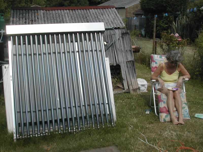
The solar water heating panel has now been installed on the workshop roof, and is contributing on sunny days.

The workshop has been fitted out with a new workbench and space for my homebrew-power battery and inverter equipment. The Lister veg-oil powered generator has been moved into its new position in the engine shed - behind the workshop.

The decked area provides somewhere to sit out in the evening, away from computers and televisions, and we now have a wood fired chiminea, which acts as a focal point and some welcome warmth on these chilly August evenings. We burn offcuts of scrap wood that were left over from the shed and decking.

Last weekend, with the help of my nephew Adam, I completed the insulation of the workshop and the engine shed. Not only does this make it warm in winter and cooler in the summer, but the plasterboard backed insulation in the engine shed helps to absorb the engine noise.

The aim is to have the veg-oil generator set re-installed by the beginning of September.

There will be plenty of time to work on this during the Bank-Holiday weekend at the end of this week.

Sunday, June 03, 2007

June's Busting Out All Over!


At last, after the dreadful cold, wet weather at the end of May, early June has provided us with 3 days of sunshine so far. The rain gave the garden a much needed watering, and now plant life is really starting to pick-up the pace.

Temperatures are in the low to mid 20's, and the garden is buzzing with life. With the recent rain, the grass is growing rapidly and needs cutting each week.

Our garden is a long, narrow strip of level ground about 20 feet wide and 180 feet long. It is broken up into distinct areas, with a 50 foot lawn, greenhouse and various sheds.

The topsoil is reasonably fertile for the first 12" or so, with heavy claggy clay lying beneath this. The garden has been cultivated for the last 100 years, since our house was built, with lots of ashes and composted kitchen and garden waste used to return the goodness into the soil.

Whilst we have in the past dug vegetable beds, we have chosen this year to go for easy maintenance grow-bags, planters and tubs.

This year we have decided to grow a few vegetables and have already tasted our first home grown cucumber (photo). These mini cucumbers are amazing, growing at a rate of about half an inch per day.

We have marrow, courgettes, cucumbers, peppers and tomatoes all planted in grow-bags or troughs. Further down the garden our potato plants, sown in early May are now flourishing, and should provide us with a few tasty potatoes in July and August.

For the next 3 or 4 months, living should be easy. Our solar panel provides sufficient hot water for our daily needs, and there is no need to heat the house.

Whilst we are under no illusion that it would be possible to feed ourselves from our little allotment sized plot, nothing can be so good as the experience of growing a few vegetables, nurturing them and tasting fresh garden produce with the summer salads.

Tuesday, March 27, 2007

The New Workshop and Engine Shed


I have been making the most of the better weather in early March to press ahead with a very much needed new workshop and engine shed.

Here is a front view of the new shed. It faces southwest so that it catches the afternoon sunshine.

The shed is 9m from the house and makes use of the concrete base from the old shed.

This base has been very much extended now 6m x 3m and incorporates an isolated area to mount the two engines for my household combined heat and power system.

The workshop is heavily insulated so that it is a comfortable workplace all year round. Behind the workshop is the engine shed area which houses the two engines (main and back-up) their generators and all the other ancillary equipment such as the thermal heatstore and the wood burning boiler system.

As well as containing the vegetable oil fuelled generators, the shed will have my solar water heater fixed to the front roof for maximum sunshine.

A pair of insulated hot water pipes buried in a trench connect the systems in the shed back to the household heating system.

With the engine running during the day and the wood fired boiler taking over at night, the renewable energy systems in the shed will be able to provide complete heat and power for my house.

The whole project can be found on my webpage www.powercubes.com/listers_3.html

Tuesday, November 28, 2006

Tales from the Engine Shed


Today I have reached a milestone achievement with my waste vegetable oil generator system.

The 2nd hand emergency lighting unit that I hauled back from Wales last December is now working as a 5kW pure sine wave inverter.

That's it on the right of the photo - about the size of a single wardrobe. Two inverters units rest side by side and the bottom two shelves contain the eight 100Ah batteries.

I tried earlier in the year to get the inverter to run, but without success, solely becausse I was not giving it enough voltage. It has a special circuit that doesn't activate until it sees about 118V dc and then it springs into life. This is designed so that it won't work unless the batteries are in a good state of charge.

Likewise the inverter senses when the batteries get too low, and cuts the inverter power. This prevents the the inverter from completely flattening the battery.

The inverter is now running and producing up to 5kW of power, but the key thing is that it produces a pure sine wave at precisely 50Hz and 237V, which is essential for running modern equipment such as PCs and believe it or not, washing machines!

I now have to learn how to use the inverter to efficiently power my house. Clearly I don't need the full 5kW all the time, and at the dead of night, the house uses only about 100W keeping the fridge and freezer running.

The key to efficient use, will to run the Lister at different speeds, depending on how much demand for power is put onto the inverter. When more power is demanded, an electromagnetic solenoid will open the fuel rack to allow more power from the engine.

When idling, the engine produces about 600W of power, which is more than enough to run the house during the day, and if a heavy load is turned on, such as a kettle, the batteries take up the load for the time it takes to boil the kettle, and the engine returns to idle. In this way of working, it uses just less than half a litre of waste vegetable oil per hour, so a gallon will last about ten hours, or a complete daytime run.

Another new addition to the engine is an exhaust gas heat exchanger. A friend made this out of stainless steel for me to test. It is basically a water cooling jacket around the hot exhaust pipe, which extracts the wasted heat and uses it to heat up the domestic hot water. It will produce a full tank of hot water in just 2 hours of running.

So I am all set to take my first tentative steps to off-grid living, in the heart of Suburbia.
This weekend I expect to have completed the wiring and the change-over switch which will allow me to disconnect from the grid and over to the Lister generator.

Saturday, September 23, 2006

Autumn Almanac

Once again we return to the transitional time of year between summer and autumn. After a hot, dry summer, the rain returned in August and has brought renewed vigour to the garden.

The grass is green again, and putting on a final spurt of growth before the colder weather and shorter days.

In the garden, there are fruits abundant, with apples, rosehips and blackberries all at their best. Unusually, my two Elder trees have failed completely to produce a single bunch of berries.

This is the time of year when we really ought to be thinking about the forthcoming colder weather, but with morning indoor temperatures still in the low 20's, here's hoping that we can keep the heating off for at least another few weeks. When the temperature of the living room reaches 17 C, that will be my cue to start the heating.

The last 12 months has been a period of re-assessment. Whilst I must admit that I have not achieved half of the things I set out to do, I must admit that I have a clearer understanding of how I can move towards the sustainable lifestyle that I seek.

In the early summer, I re-read, George Orwell's "The Road to Wigan Pier". This is a bleak description of life in the northern industrial towns during the mid-1930s. It is an examination of the poverty and deprivation that these areas faced in the years between the wars. Orwell visits the households of unemployed miners, and clearly accounts for the squalour and malnutrition that existed in Britain within living memory. Whilst modern life may not be perfect, without a shadow of a doubt, we've never had it so good.

Another formative read this summer, was Jim Howard Kunstler's "The Long Emergency", as reviewed in an earlier post. Again an apocalyptic narrative of what is likely to befall the western world as fossil fuels become scarce.

In preparation for the coming winter, Elaine and I are investing in a wood burning stove with back-boiler.

http://www.sussexwoodstoves.co.uk/

Whilst this is likely to cost the best part of £2000 when professionally installed, mainly because of the cost of having a twin-skin stainless steel liner fitted in the flue, we are confident that it is going to offset about £400 of natural gas per year, and with a family friend able to keep us supplied with logs, we believe that we are looking at a payback of around 5 years.

The key advantage of the woodstove is that is will provide a significant boost to the heating of the living room area, where Elaine likes to spent the winter evenings reading. The radiant glow from the stove and the higher room temperatures will make for cosy evenings. Fortunately this property was built with a substantial fireplace in every room, and it will be an easy job to recommission the cavernous hearth of the living room.

Woodstoves, although more efficient than open fireplaces, are not as efficient as gas boilers in transferring the heat from the burning wood into the water. As a consequence, a lot more wood has to be burned to get reasonable output from the back-boiler, and this might lead to excessive temperatures in the room containing the stove. However, Elaine likes a comfortably warm room, so I don't consider this a major problem - provided that I can keep sawing as fast as she's stoking!

The Ice Man Cometh?


The energy meter that I fitted to my fridge and freezer a year ago shows a consumption of 569 kWh in the last year - a little more than 1.55kWh per day, or 19.2% of my total consumption.

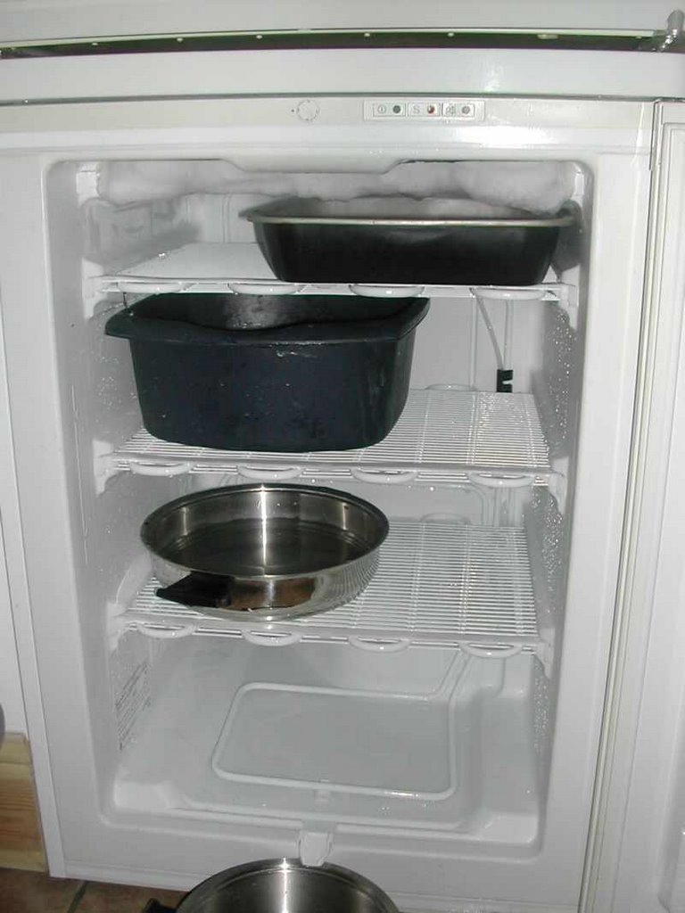
I reckonned that this was a little high, so I watched the energy meter a while and noticed that the freezer was taking a continuous 50W, instead of cycling on and off.

I suspected that it was time for a defrost, so that the cooling coils can work more efficiently. A couple of hours spent with some hot water in baking trays soon had the freezer completely ice free!

At the same time I turned down the freezer thermostat from 5 to 4, as clearly the freezer had been running very cold.

The strategy worked and the fridge/freezer daily consumption has halved, resulting in an overall 10% saving in my electricity consumption.

It's now a year since I started my "E-Plan" electricity diet, there have been some successes, some failures, and plenty of room left for improvement.

My Excel Spreadsheet, of meter readings tells me that I have used 2954 kWh of electricity in the last 365 days, which is an average of 8.1 units per day.

The main problem has been remembering to turn off devices at the end of the day, particularly those with clocks, such as the microwave, which over the course of a year will use about 27 kWh - keeping its clock running!

Also the TV in the bedroom is always on standby drawing 3.5W - another 30kWh per year.

One of my pastimes is listening to the radio whilst I work. There is always something intelligent to listen to on BBC Radio 4, and it helps pass the time, whilst working alone from home. This morning I discovered that my mini-HiFi had a standby current of 6W, and only 7W whilst playing the radio - perhaps its time to re-instate my solar/clockwork radio.

One other revelation was that the power supply for my solar panel circulation pump, that comes on for 8 hours per day on a timeswitch, was using 25W doing nothing and 28W when pumping. I have now replaced it with a plug-in supply that uses just 7W whilst pumping. This will save at least another 52kWh per year.

My workroom/Office is central to everything I do, and has it's own power budget. Some time ago I speculated on the "200W Office", and this is something that I have tried to adhere to. As the Office is powered for nearly 18 hours per day, it is essential to keep the parasitic loads to a minimum. Typically it runs at around 175W, during the day and 200W when I need extra lighting.

One shocking fact, is that when I do turn off the PC at the end of the day, the Office is still drawing 20W of power keeping things on standby. This situation must be remedied and I am going to fit a master switch to the office, allowing everything to be turned off overnight.

Having totalled up all of the parasitic loads, i.e. things that consume power yet do nothing useful, I found that they were consuming 206 kWh of electricity per year - exactly 7% of my annual electricity consumption. To put that into perspective, that's enough electricity to heat my hot water for 30 days.

Having completed a year of the diet, I am eager to make further improvements, and see if I can get my consumption down to just 7.5kWh per day, by remembering to habitually turn off the unwanted devices.

Watch this space.

Saturday, August 19, 2006

This Ole House

Yesterday, August 18th, 2006 was the 6th anniversary of Elaine and I moving to our house in Suburbia.

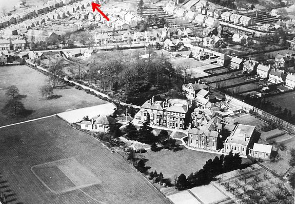
This house was typical of those built at that time in the expanding towns. This ariel photograph from the 1930s shows the surrounding area - our house arrowed in red.

The house was built in 1905, at a time when Britain was fuelled by coal, and powered by steam. This is reflected in the design of the house, where each room was intended to be heated by an open fireplace, burning coal.

In the kitchen was a range which provided fairly primitive cooking facilities, and possibly a small oven. In 1905, having a kitchen, in a separate extension to the main living room would have been the height of modernity. Thirty years earlier there would have been no kitchen and all food preparation and cooking would have been done in the back parlour.

In 1905, the only water supply was from a single cold tap in the kitchen, usually set over a Belfast sink. The water pipe also went to the cistern that flushed the outside toilet, and also to the large galvanised water tank in the attic.

There is no evidence to suggest that the house had hot water, when first built. Water would have to be heated in a kettle over the stove. A hot water supply was added later, using a cast iron back-boiler, that was placed behind the grate of the fireplace in the living room. Copper pipes, chased into the plaster, carried hot water upwards to a tank in a cupboard in the first floor bedroom. The system ran using the principle of thermosyphoning, where the lighter hot water rose up into the top of the tank, displaced by the cooler water that descended to the boiler from the bottom of the tank. The system was simple, as no circulation pump was needed - ideal for the 1920s when there was no electricity, but of dubious efficiency. How much coal would be needed to properly heat the 25 gallon tank?

Life was fairly straightforward in the early years of the 20th century. Redhill was a thriving railway town, within 30 minutes commute of the centre of London. The town was full of shops and traders of all nature, and only a half mile walk away. Shopping would have been done several times a week, based on the fact that before refrigerators, food would not remain fresh, and before car ownership, there was a limit to what could be carried back from the town centre. Most traders would deliver larger items by horse and cart, in particular the coalman, weekly with sacks of coal. Bakers, fishmongers and milkmen often sold their provisions from horsedrawn delivery carts in the outer lying areas of the town, effectively capturing more custom from those that could not get into town, such as the elderly or mothers with young children.

In the 1880's, the road was laid out, on a former orchard. Plots were allocated, of roughly a tenth of an acre, most being 20 feet wide and 250 feet long. The tenth acre plot allowed plenty of garden for growing vegetables, keeping chickens and the like. It is rumoured that a long gone neighbour once kept pigs in a sty at the bottomofthe garden.

Judging from the mix of house styles in the street, and the dates on some of the houses, the road was developed by several builders over a period of about 30 years.

The house is solidly built from traditional materials, and much of the builder's skill is evident on what they could achieve with just 4 or 5 basic materials; brick, slate, mortar, timber and glass.

Built at a time when coal was cheap, there was no real need to have a good level of insulation, and so the outside walls are a 9" solid brick construction. The slate roof was laid without an underfelt and so the attic space was cold and draughty in winter and unbearably hot in summer.

Over the last 100 years, about 4 families have lived in this house, with each successive owner making improvements, to suit changes in taste or fashion, and to improve comfort. My intention is to improve the property in such a way that reduces its energy requirements, lowers its carbon footprint, and allows life to continue according to a Sustainable Roadmap.

The construction of the house is not ideal for energy reduction, but as it was built with a very low standard of insulation, large improvements could be made. The attic rafters space can be insulated with a modern insulation board that will considerably reduce the heatloss through the roof.

The 9" solid brick walls are not particularly good from a heat loss point of view, but the thermal mass of the internal walls and chimneys, is good at retaining heat over long periods and this helps to stabilise the room temperature.

Last year, an efficient natural gas heating boiler was installed, and this has reduced the gas consumption from 20050 kWh to just 16400 kWh in this last year.

Solar water heating has allowed us to turn off the gas water heating for the whole of the summer, and so daily gas consumption has averaged just 1.5 kWh per day - all of which is attributable to cooking.

Electricity consumption is also much reduced, from 3812 kWh last year to just 2915 kWh this year. This is as the result of turning off unused appliances such as TV and video, fitting low energy light bulbs and making sparing use efficient use of low energy washing machine, dishwasher and kettle, all of which heat water by electricity. The 3kW immersion heater that once heated the hot water tank, and used a lot of electricity throughout summer 2004 is now very seldom used.

A shower has also been installed, that has reduced our daily water usage considerably, using just 20 litres of water at 38 degrees C, compared to a bath which was typically 135 litres. It's even better when you realise that the shower has been entirely heated by solar energy.

Now that I have minimised the existing fossil fuel consumption of the house, the next stage is to install renewable fuel systems, that will further reduce the fossil fuel footprint of the house and yet maintain a comfortable and rewarding lifestyle.

Over the next few posts, I hope to discuss my Sustainable Roadmap, and the implications it will have on life in Suburbia.

Thursday, August 03, 2006

The Long Emergency


The Long Emergency is the term given to a series of converging catastrophic events identified by author and analyst James Howard Kunstler.

His book, written in early 2005, describes the world events brought about during the age of cheap oil, and the likely consequences for all of us, as we now move inexorably into an era where oil is no longer cheap.

Kunstler examines world history over the period of the last 200 years, and identifies the processes and events that brought about a world economy fuelled by and entirely reliant on continuing supplies of fossil fuels.

World oil production is in terminal decline. Natural gas reserves have already peaked and yet we are all still "sleepwalking into the future" - a future without oil.

Kunstler focusses mainly on the suburban American lifestyle and the effects that a forthcoming oil shortage will have on it, but for anyone reading this book in the western world, the outcome is likely to be the same.

Depressing, fatalistic and apocalyptic, Kunstler's examination of the modern oil dependant lifestyle, reveals the truth about the route we took to get to this situation, and points out that the options for our exit strategy are extremely limited.

The Long Emergency was a gripping read. I can recommend it to anyone who wants to awaken from a century of sonambulism.

Sunday, July 30, 2006

Summer Time - And the Livin's Easy!


It' now a year since we built the extension onto the house and made several improvements to the downstairs.

Our living room is not only brighter, with the addition of two extra windows, but the extra insulation used in the new extension has made it cooler in summer, and less draughty in winter.

The new high-efficiency condensing gas boiler has saved over 3500 units of gas in the last year, which at today's prices is worth over £100.

The solar water heating panel is providing us with sufficient hot water for our summertime needs, which means that the boiler is not used for hot water for June, July and August.

The new shower has been very popular and it has not only reduced our water consumption, compared to the bath, but one can feel particularly smug when the water was heated only by the solar panel.

The "electricity diet" has been running since last September,and we have managed to keep our average consumption down to just 8 kWh per day.

We have found that even with sensible use of the dishwaster and washing machine, that our daily power consumption seldom exceeds 10kWh.

July has been particularly hot, so my best investment was a cheap electric fan, which makes the workroom comfortable even on the hottest of afternoons. It uses only 40W making it very economical to run, and a direct localised cooling breeze is far more effective, than having to install costly air-conditioning equipment. At under £15 - it was a bargain!

However it is easy to get complacent during the hot summer months, and forget that within only 8 weeks or so, it will be time to put the heating on again.

This autumn should see the start of my renewable fuelled heat and power system, which has not been needed in the summer months.

In addition, our new woodstove and boiler will be installed in September, ready for the chilly Winter nights.

Saturday, July 01, 2006

Hotter Than July


Today is July 1st and it is expected to be the hottest day so far this year.

At 3pm I measured the temperature in the shade of my apple tree at 30 degrees C.

The solar panel is working well with an outlet temperature of 66.5 C, already having got my water tank up to a pleasant 40C - ideal for free, solar heated showers. It will probably reach 45 degrees by the time the sun passes by the panel.

The solar panel receives head on sunshine from about 3pm, at round about the same time that Elaine decides that it could well be warm enough to sit outside!

Personally, I prefer the shade of the apple tree, and often sit there in the early evening, to wind down after peering into a computer screen for 8 or 10 hours.

Start it Up!


I have been busy fitting a starter motor to my veg oil fuelled Lister generator. I had managed to acquire a powerful 6kW dc permanent magnet motor some time ago, and it was just a case of making a suitable bracket and belt driving it to the Lister.

The motor is coupled by pulleys and belts to the alternator shaft, and runs at 1200rpm when the alternator is doing the correct 1500rpm speed for 50Hz ac electicity.

The photo opposite is taken from above showing the twobelt drives linking engine to alternator and alternator to starter motor.

Last night I powered the starter for the first time,using 12V to begin with and then working up to 36V supplied from 3 large leisure batteries.

The starter works well, and certainly beats cranking by hand.

This type of motor also works very well as a generator, because it is permanently connected to the engine via the belts, and when the engine is turning the alternator at 1500rpm, the starter makes 134V dc, which can be fed straight back into the battery bank of my rather big, 5kW inverter.

The much appreciated sunshine for the last few weeks has allowed us to get our hot water almost entirely from the Navitron solar water heating panel. On dull days I start the Lister engine up for an hour, and the electricity generated goes straight to the immersion heater in the hot water cylinder, via a direct cable.

We have not used any gas for water heating for the last month. At this time last year our old gas boiler was using 6kWh a day just burning the pilot light. Now we only use gas for cooking, and average 1.5 units per day.

With the hot summer weather, it is difficult to remain focussed on the aims of producing a self-built renewable heat and power system capable of supplying all my winter needs.

The engine is now running reliably on waste vegetable oil, and the new starter makes it so much easier to crank it over.

The hombrew power system is rapidly starting to outgrow my humble 8 x 6 shed, so I am planning a simple extension made from exterior plywood on a timber frame.

So much to do, time to get cracking!